Ampeg Plate Follower Phase Inverter
Here we consider a circuit you won't find in a Fender or Marshall: a paraphase phase inverter with a plate follower for the second stage. It is integrated into the signal chain of the venerable Ampeg M-15.
"The nifty 1961 M-15, covered in navy random-flare vinyl, is a prime example. It might have been at home sitting behind Wes Montgomery or Kenny Burrell on a small club stage - or maybe gracing accordionist Dick Contino's back line. But if you look beneath the hood, it carries a mix-and-match bundle of ingredients found in a couple variations of a highly desirable blues and rock amp from another maker, so there's no logical reason this jazzer's combo can't do many of the same tricks, accordion inputs or not." 1 -Dave Hunter
A Traditional Paraphase Phase Inverter
Before investigating the intricacies of the M-15, let's look at a traditional paraphase phase inverter, as found in the Fender Deluxe 5A3.
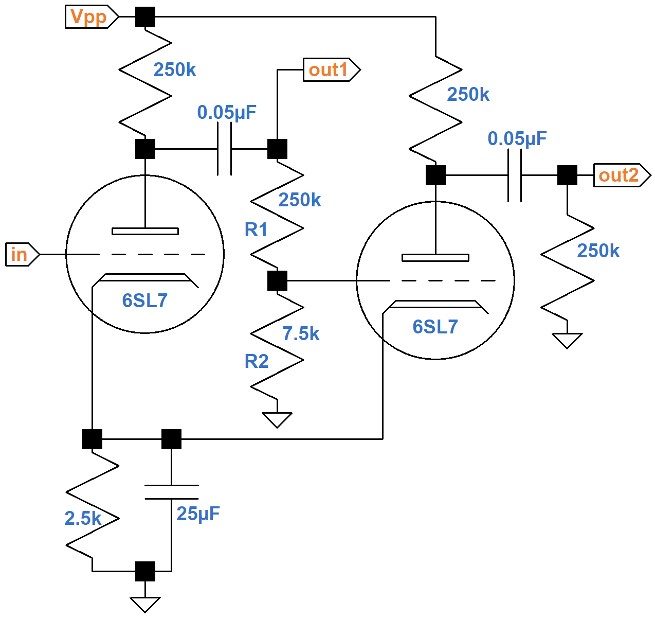
The 6SL7 is a high-mu twin triode. Its amplification factor is typically 70, which is more than a 12AT7 but less than a 12AX7. For AC signals, the first stage has an effective AC plate load equal to the 250KΩ plate load resistor in parallel with the 2nd-stage grid-leak resistance:
250kΩ || 257.5kΩ = 127kΩ
The shared 2.5kΩ cathode resistor is fully bypassed by the 25μF capacitor. 6SL7 plate resistance is typically 44kΩ, so first-stage voltage gain is
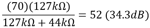

|
Guitar Amplifier Electronics: Fender Deluxe - from TV front to narrow panel to brownface to blackface Reverb |
The second-stage voltage amplifier needs to invert the signal without amplifying it. Otherwise the second power tube grid gets a higher signal level than the first. From grid to plate the second stage has the same gain as the first, so ideally the voltage divider formed by R1 and R2 should have a voltage "gain" of
1 / 52 = 0.0192 (-34.3dB)
Moreover, to match the 250kΩ AC load of the second output, the sum of R1 and R2 needs to be 250kΩ. Fender's resistor values represent a compromise to match standard resistors. The Deluxe voltage divider has a gain of 0.0291 (-30.7dB) and the AC load is 257.5kΩ.
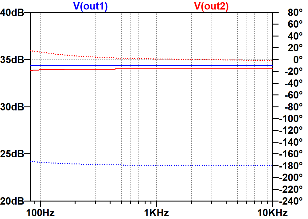
Here are the results of a SPICE AC analysis simulation.2
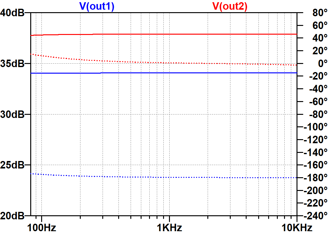
The dotted traces and scale to the right show that the second output is 180 degrees out of phase with the first output, which is ideal. The solid traces and scale to the left, on the other hand, show that the second output has almost 4dB more gain. Fender could have achieved better balance by using a 4.7kΩ value for R2, but chose to allow more gain for the second output.
|
Guitar Amplifier Electronics: Basic Theory - master the basics of preamp, power amp, and power supply design. |
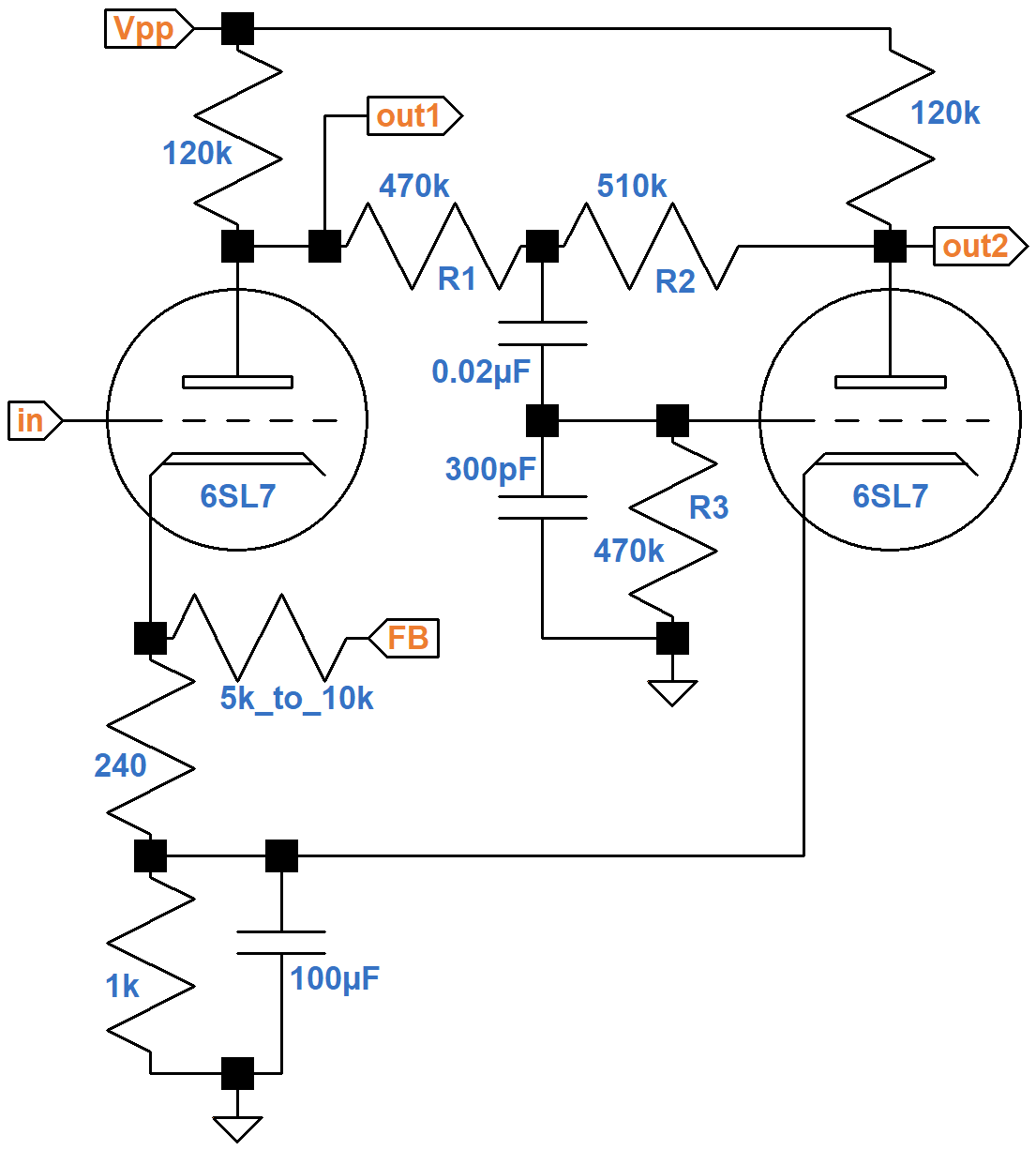
The Ampeg M-15 Circuit
Ampeg's phase inverter is a bit more complex, but implements the same concept: a second-stage voltage amplifier that inverts the signal without amplifying it.
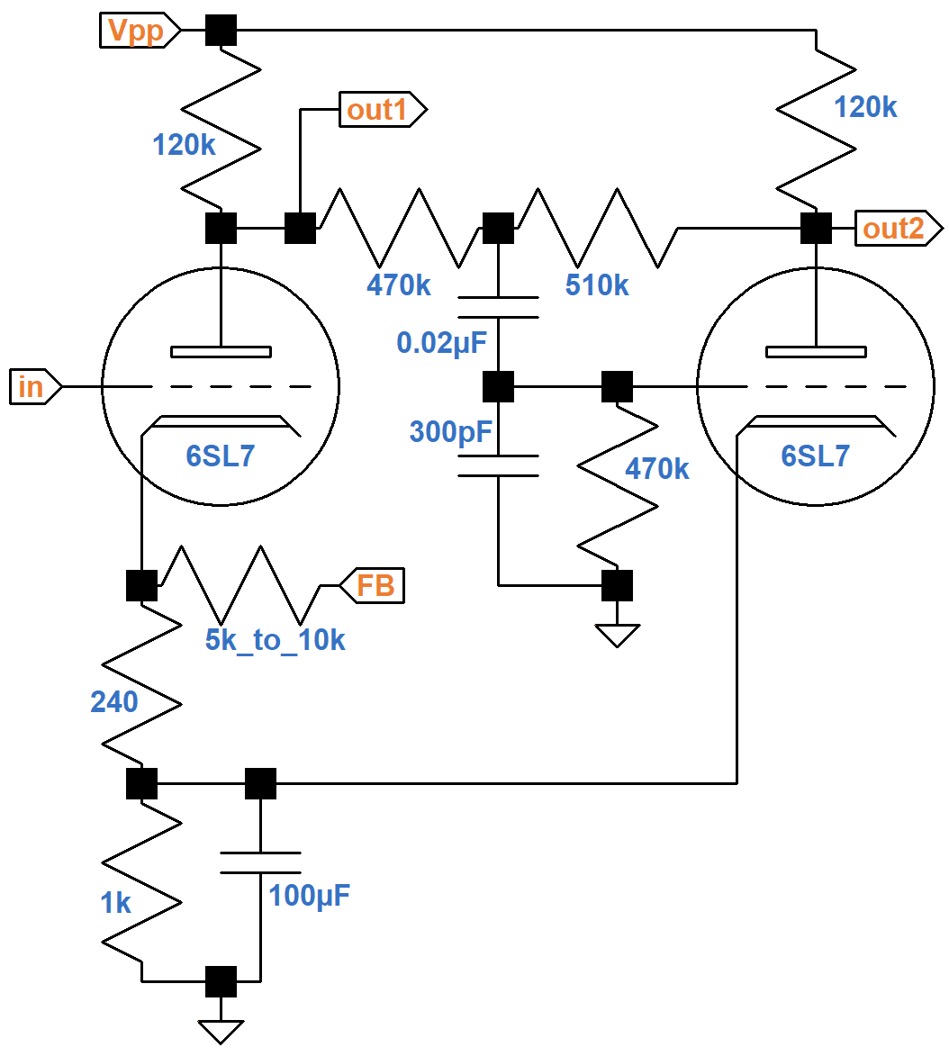
The FB input is feedback from the 8Ω tap of the output transformer secondary. The cathodes share a fully bypassed 1kΩ cathode resistor, which matches Fender's configuration, but a 240Ω resistor is added to the first stage to create a feedback input.
The 0.02μF capacitor blocks DC from the high-voltage plates, so the grid of the second stage is at DC ground potential via the 470kΩ grid leak.
|
Fundamentals of Guitar Amplifier System Design - design your amp using a structured, professional methodology. |
To see how Ampeg achieves its design objectives, let's create an equivalent circuit for midrange audio signals. The 100μF capacitor acts as a short circuit for audio signals, so we can assume the second stage cathode is connected to AC ground. The plate supply voltage VPP is shorted to ground for audio signals by the large capacitor (not shown) of a power supply ripple filter. The 0.02μF capacitor acts as a short circuit for midrange signals. The 300pF capacitor is very small, only coming into play at the high end of treble.
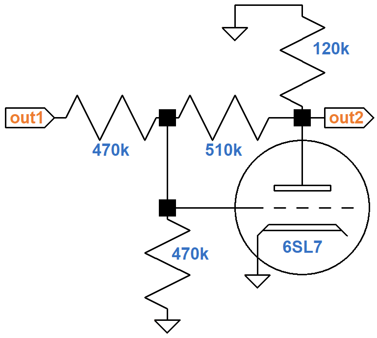
When the signal voltage at node out1 increases,
it causes the grid voltage to increase via the
voltage divider formed by the 470kΩ resistors.
Since the tube circuit is an inverting amplifier,
the signal voltage at out2 decreases.
Without the 510kΩ feedback resistor,
the magnitude of the output signal swing would be much greater than the
signal swing at the grid.
With the resistor in place, negative feedback
ensures that the second output has the same signal amplitude as
the first output: when the voltage at out1 increases,
the voltage at out2 decreases by the same amount.
|
Guitar Amplifier Electronics: Circuit Simulation - know your design works by measuring performance at every point in the amplifier. |
A circuit with no gain is reminiscent of a cathode follower,3 which gets local feedback from the cathode. Ampeg's circuit gets feedback from the plate and is therefore known as a plate follower. The key difference is phase - a cathode follower's output is in phase with the input. A plate follower's output is 180 degrees out of phase.
Balance between the two phases is set by specifying resistors R1 and R2.
Their total resistance needs to be high to create a light plate load that does not compete with the power amp's 270kΩ grid-leak resistors. If the 6SL7 provided infinite gain without feedback, then the gain of the second stage with feedback would be equal to the ratio of R2 to R1. For a balanced paraphase inverter the resistor values would be the same. For a real-world triode amplifier, R2 needs to be slightly greater than R1 to reduce feedback and achieve balance.
If it is large enough, R3 has little effect on balance since it shunts the grid for both the signal and feedback. The 300pF capacitor prevents radio-frequency oscillation.
An AC analysis simulation shows that the M-15 phase inverter is more balanced than a stock 5A3.
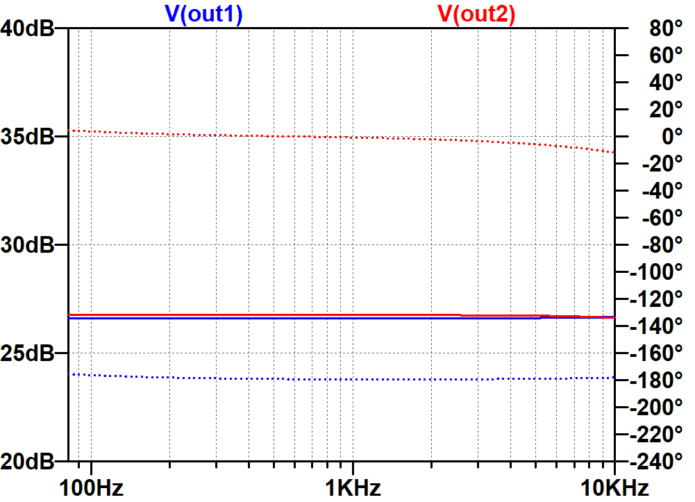
(For the simulation, negative feedback was set for about -6dB closed-loop gain compared to open-loop gain.) For a fair comparison, here is the response for Fender's circuit if its 7.5kΩ resistor is replaced by 4.7kΩ.
Anode Follower versus Traditional Paraphase
Fender's traditional implementation of the paraphase second stage uses a voltage amplifier without feedback. A real-world triode creates distortion for large signals. When a large input signal swings positive, the first-stage triode creates more voltage gain than when the input swings negative. Because it is an inverting amplifier, this drives the first power tube grid more negative than positive relative to its DC operating point. The input to the second stage amplifier is similarly driven more negative than positive. If the second triode were perfectly linear, its inverted output would drive its power tube more positive than negative. The second stage introduces its own nonlinearity, however, which counteracts the distortion introduced by the first triode. For a large, symmetrical input signal, the first output is more asymmetrical than the second output when driven hard. The asymmetry results in second-harmonic distortion that is unique to a traditional paraphase.
Ampeg's second stage has a generous amount of negative feedback. This reduces its distortion and flattens its frequency response.4 It also lowers the output impedance driving the second power tube. This gives Ampeg's phase inverter and power amp a distinctly different character.
References
1Dave Hunter, Amped, (London: Voyageur Press, 2012), p. 90.
2Richard Kuehnel, Guitar Amplifier Electronics: Circuit Simulation, (Seattle: Amp Books: 2019).
3Richard Kuehnel, Guitar Amplifier Electronics: Basic Theory, (Seattle: Amp Books: 2018), pp. 79-87.
4Richard Kuehnel, Guitar Amplifier Electronics: Basic Theory, (Seattle: Amp Books: 2018), p. 152.