Davoli Bootstrapped Phase Inverter
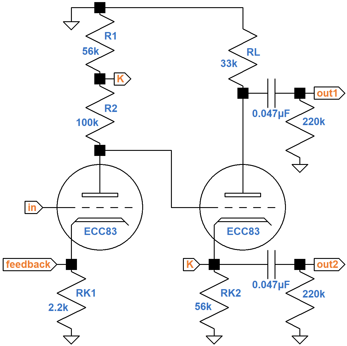
The circa 1965 Davoli Model 207 guitar amplifier from Parma, Italy has an unusual phase inverter with a split plate load (resistors R1 and R2).
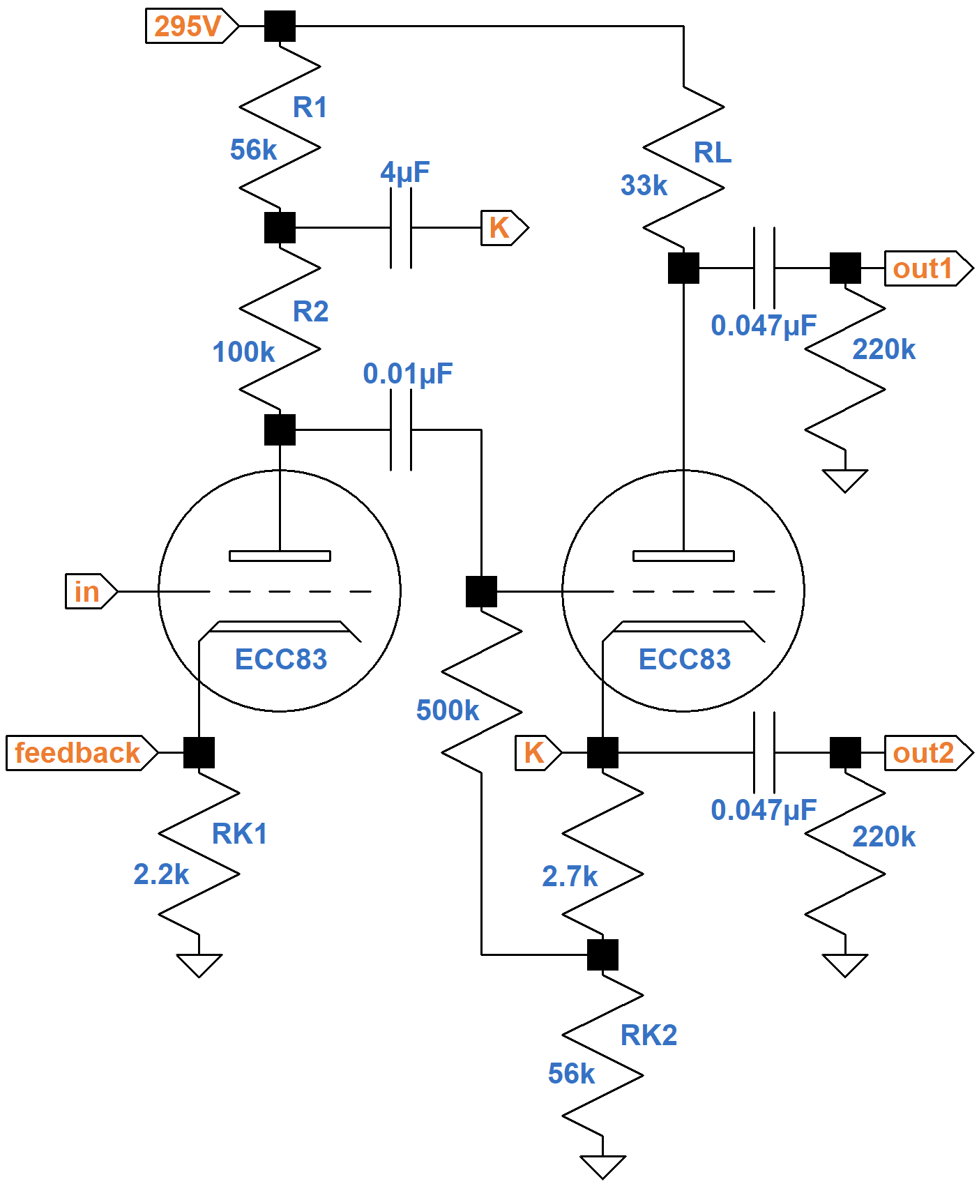
The cathode of the cathodyne phase inverter1 is connected between the two resistors via a 4μF DC-blocking capacitor. Without this connection, the first stage is a traditional voltage amplifier with a feedback insertion point at the cathode, just like the second stage of the Fender Champ 5E1, for example. To quantify how this connection improves performance, we could apply Kirchhoff's Voltage Law over a large number of loops and develop some extremely long formulas for voltage gain. The results, however, would not provide any insight into how Davoli's design works. Instead, let's simplify the circuit step-by-step to discover its core features.

|
Guitar Amplifier Electronics: Fender Deluxe - from TV front to narrow panel to brownface to blackface Reverb |
DC Operating Conditions
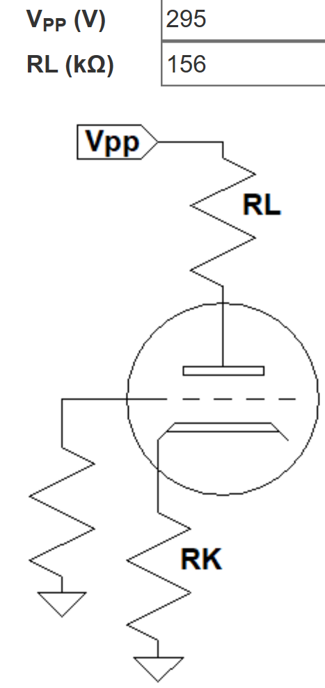
The 0.01μF capacitor blocks the high DC voltage of the upstream plate from the downstream grid, leaving the 500kΩ and 2.7kΩ resistors to establish the DC operating point for the phase inverter. As our first step in circuit simplification, let's determine the DC operating conditions and then transition to an equivalent AC circuit that eliminates these three components.
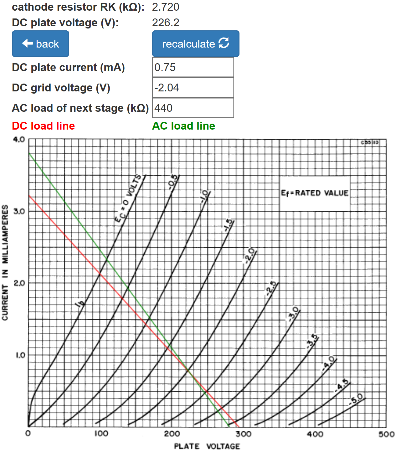
According to the 12AX7 calculator, the 2.2kΩ cathode resistor creates a neutral -1.6V grid bias for the voltage amplifier.
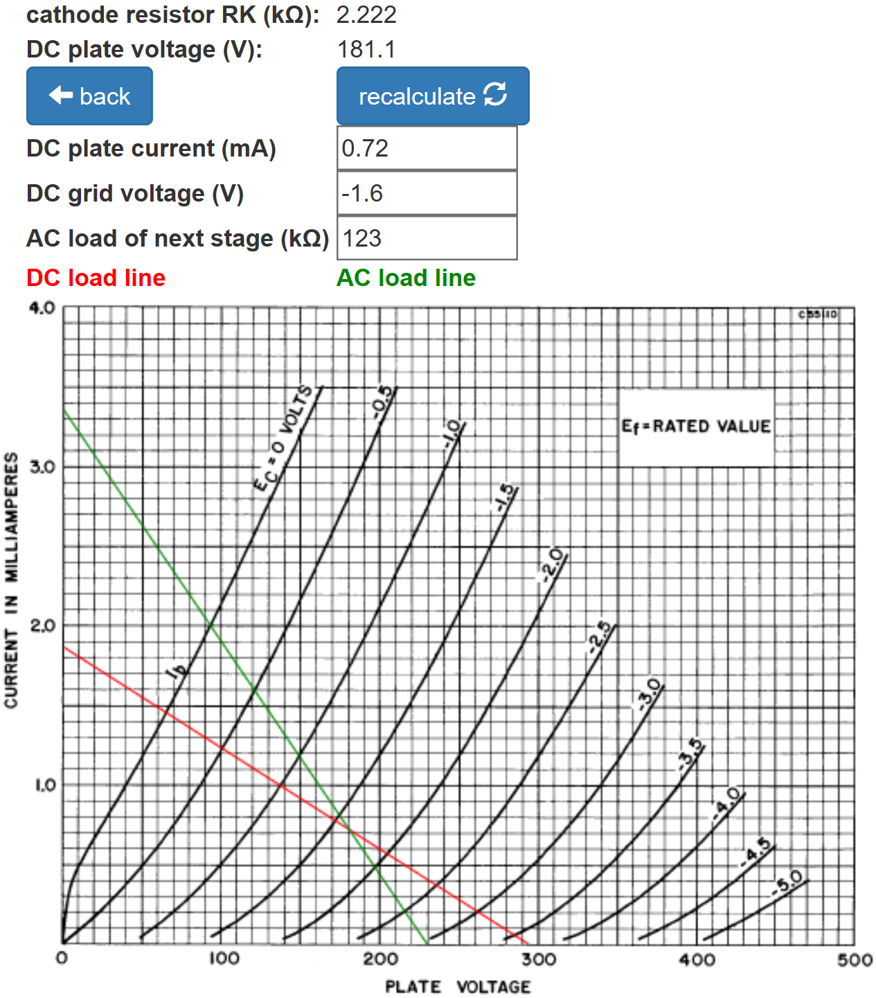
(The AC load is extremely light, so an arbitrary value of 123kΩ has been entered to provide a convenient marker for the DC operating point.)

|
Guitar Amplifier Electronics: Basic Theory - master the basics of preamp, power amp, and power supply design. |
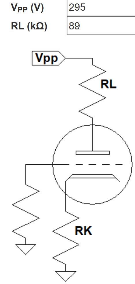
The phase inverter has 33kΩ at the plate and 56kΩ at the cathode for a total of 89kΩ. It is biased more coldly than the first triode but still has plenty of plate voltage swing to drive the power amp to full power.
AC Operating Conditions
The 4μF capacitor is designed to block DC. For audio signals down to 82Hz, the lowest note on a guitar with standard tuning, the capacitor acts as a short circuit. The phase inverter grid draws no current and the 500kΩ resistor passes very little current. The 2.7kΩ resistor used to establish DC grid bias is much smaller than the 56kΩ cathode resistor. The 295V plate supply is at AC ground. Given these observations, the AC circuit can be simplified considerably without sacrificing much accuracy.
Computing the reduction in gain from the 220kΩ grid-leak resistors for the power amp, representing the AC load, does not add anything to our understanding of the circuit, so let's focus on unloaded gain to simplify the mathematics. The 2.2kΩ cathode resistor is unbypassed. Normally this causes a substantial reduction in gain due to negative feedback from cathode degeneration.2 It turns out that for Davoli's design there is little negative feedback, making a cathode bypass capacitor unnecessary, so as a further simplification, let's assume the cathode resistor is fully bypassed by a large capacitor, shorting the cathode to ground for audio signals.
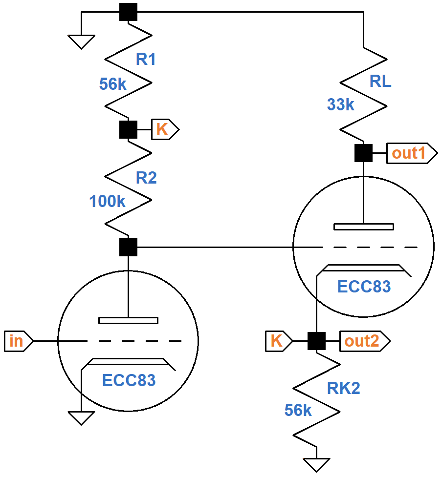
In its present form the circuit is easier to understand.
The phase inverter has slightly less than unity voltage gain
due the large 56kΩ cathode resistor.
Like for a cathode follwer,3 the AC voltage at the cathode follows the AC voltage at the grid,
which is driven by the plate of the voltage amplifier.
Because of the connection via node K, the AC voltage at the top of resistor R2 is almost the same as the
first triode's AC plate voltage.
The AC voltage across the resistor is practically zero.
The AC current through the resistor is practically zero.
For guitar signals the resistor acts as an open circuit
through which no current flows.
For the voltage amplifier, this means the magnitude of the voltage at the plate is
equal to the magnitude of the voltage at the grid multiplied by the
triode's amplification factor, which for an ECC83/12AX7 is 100.
The voltage gain of the first stage is therefore almost 100 (40dB),
which is incredible for a triode voltage amplifier.
Using feedback from the second triode to achieve this result is
known as bootstrapping.
|
Fundamentals of Guitar Amplifier System Design - design your amp using a structured, professional methodology. |
The voltage gains from the input to each of the outputs for our simplified AC circuit, assuming the 100kΩ resistor is an open-circuit for audio signals, are
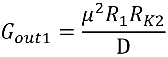
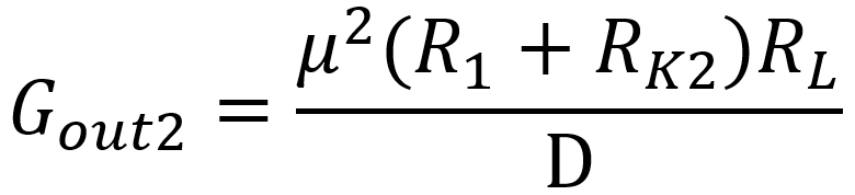
where

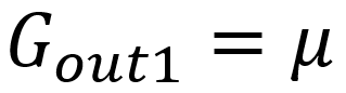
Since μ = 100 and the values of R1 and RK2 are large, the last term of D dominates the others. This makes the gains approximately
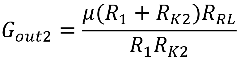
To get a voltage gain of μ at the second output, we need to set the value of the plate load resistor RL equal to
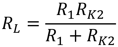
For Davoli's design, the resistors R1 and RK2 have the same value, so the plate load resistor value needed to achieve balance is simply
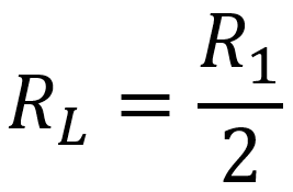
Half of 56kΩ is 28kΩ. Davoli selects 33kΩ.
|
Guitar Amplifier Electronics: Circuit Simulation - know your design works by measuring performance at every point in the amplifier. |
Circuit Simulation
Using our simplified AC circuit and approximate formulas, we estimate the voltage gain to be 100 (40dB). A SPICE AC analysis simulation4 shows that if we remove the assumption that the cathode resistor RK1 is fully bypassed, then the unloaded gain is almost the same, demonstrating that a bypass capacitor is unnecessary.
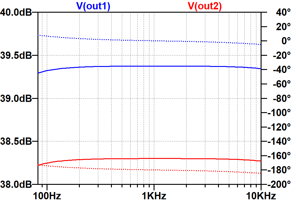
The solid traces are for gain in dB (left scale). The dotted traces are for phase in degrees (right scale). Here are the gains when loaded by the 220kΩ grid-leak resistors.
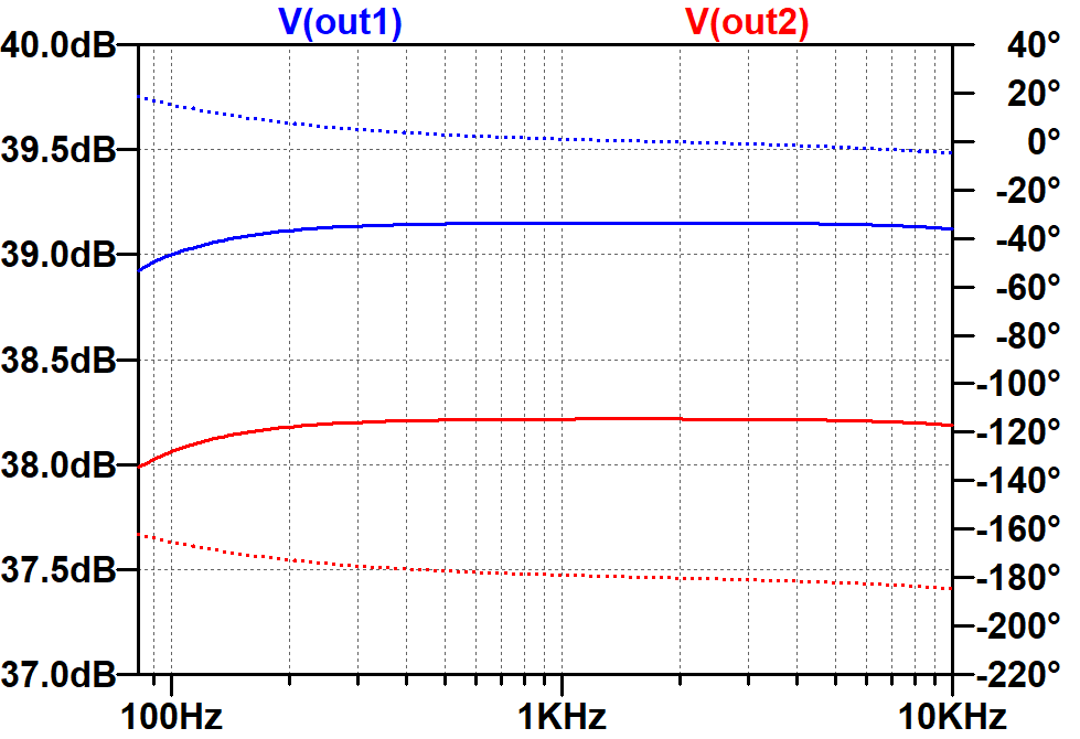
The difference between loaded gain and our estimate of unloaded gain is less than 2dB.
References
1Richard Kuehnel, Guitar Amplifier Electronics: Basic Theory, (Seattle: Amp Books, 2018), pp. 130-134.
2Richard Kuehnel, Guitar Amplifier Electronics: Basic Theory, (Seattle: Amp Books, 2018), p. 61.
3Richard Kuehnel, Guitar Amplifier Electronics: Basic Theory, (Seattle: Amp Books, 2018), pp. 79-87.
4Richard Kuehnel, Guitar Amplifier Electronics: Circuit Simulation, (Seattle: Amp Books, 2019).