Hughes & Kettner Relay Control
The Hughes & Kettner Switchblade 100 Head has two ECC83/12AX7 dual triodes and four EL34 power pentodes. The triodes implement a voltage amplifier, a DC-coupled cathode follower, and a long-tailed-pair phase inverter in classic Bassman 5F6-A style. Hughes & Kettner then expands upon its Fender/Marshall core to create a switched-channel, MIDI-controlled performance powerhouse:
- 4 channels: clean, crunch, lead, ultra,
- digital reverb, delay, modulation effects,
- fully programmable with 128 presets,
- MIDI in/out/thru, and
- parallel/serial selectable FX loops.
This vast set of features is implemented using two key ingredients: microcontrollers and relays.
Relays
The Switchblade uses TQ2-24V relays.
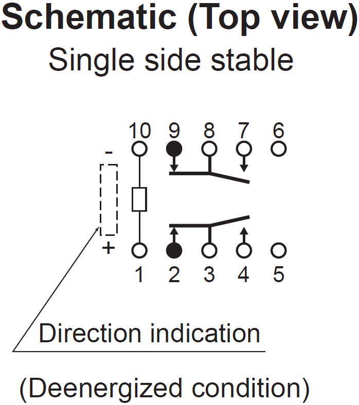
They are single side stable, so they turn on when the coil between pin 1 and pin 10 is excited and off when it is unexcited. When the coil is deenergized, pin 8 connects to pin 9 and pin 3 connects to pin 2. When the coil is energized pin 8 connects to pin 7 and pin 3 connects to pin 4.

|
Guitar Amplifier Electronics: Fender Deluxe - from TV front to narrow panel to brownface to blackface Reverb |
TQ2 series relays are available for eight nominal voltages.
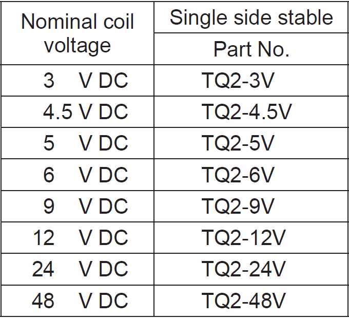
A lower voltage across the coil requires more current through it. Hughes & Kettner takes a high-voltage, low-current design path by selecting the 24V version. According to the data sheet, the pick-up voltage is 75 percent of the nominal voltage: 18V. Any voltage above 18V turns the relay "on." The Switchblade uses a 22VDC supply and puts almost all of it across the coil to activate the relay. The drop-out voltage is 10 percent of the nominal voltage: 2.4V. Any voltage below 2.4V turns the relay "off." The Switchblade uses 0V for this condition.
|
Guitar Amplifier Electronics: Basic Theory - master the basics of preamp, power amp, and power supply design. |
The coil resistance is 2.88kΩ. According to Ohm's Law, 22V across the coil draws a current of
22V / 2.88kΩ = 7.6mA
The total power dissipated by the coil is
(22V)(7.6mA) = 168mW
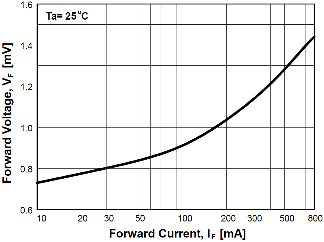
A 1N4148 diode is placed across the coil.
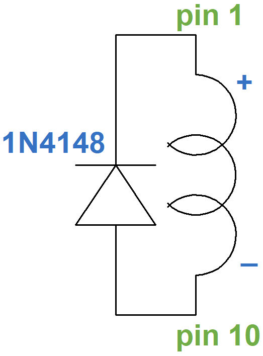
The flyback diode is used to limit the huge voltage spike that occurs when the coil is deenergized. The coil has inductance in addition to resistance. The voltage across an inductor is proportional to the rate of change in current. When deenergized, the current suddenly changes from 7.6mA to 0mA, causing the big voltage spike that has the potential to damage components connected to the relay, particularly the transistor used to switch it on and off. It also causes lots of noise. As pin 10 suddenly becomes positive with respect to pin 1, the diode limits the voltage spike by creating a low-resistance path for current to flow upwards through it. The voltage is limited to the forward voltage of the diode, which for the 1N4148 is about 1V.
For a TQ2-24V relay, the operating time, also called set time, is a maximum of 3 milliseconds from the time 24V (nominally) is applied to the coil. This includes bounce time as the switch settles into its energized position. The release time, also called reset time, is also 3 milliseconds.

|
Fundamentals of Guitar Amplifier System Design - design your amp using a structured, professional methodology. |
The Switchblade has a 10μF capacitor in parallel with the flyback diode and coil.
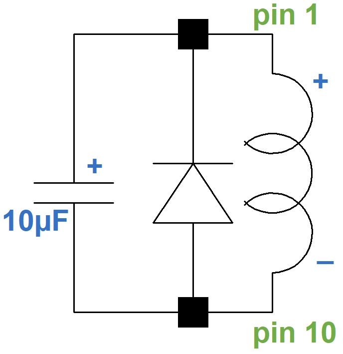
This reduces high-frequency noise created when the coil is switched, especially when it is switched off.
Transistor Switching
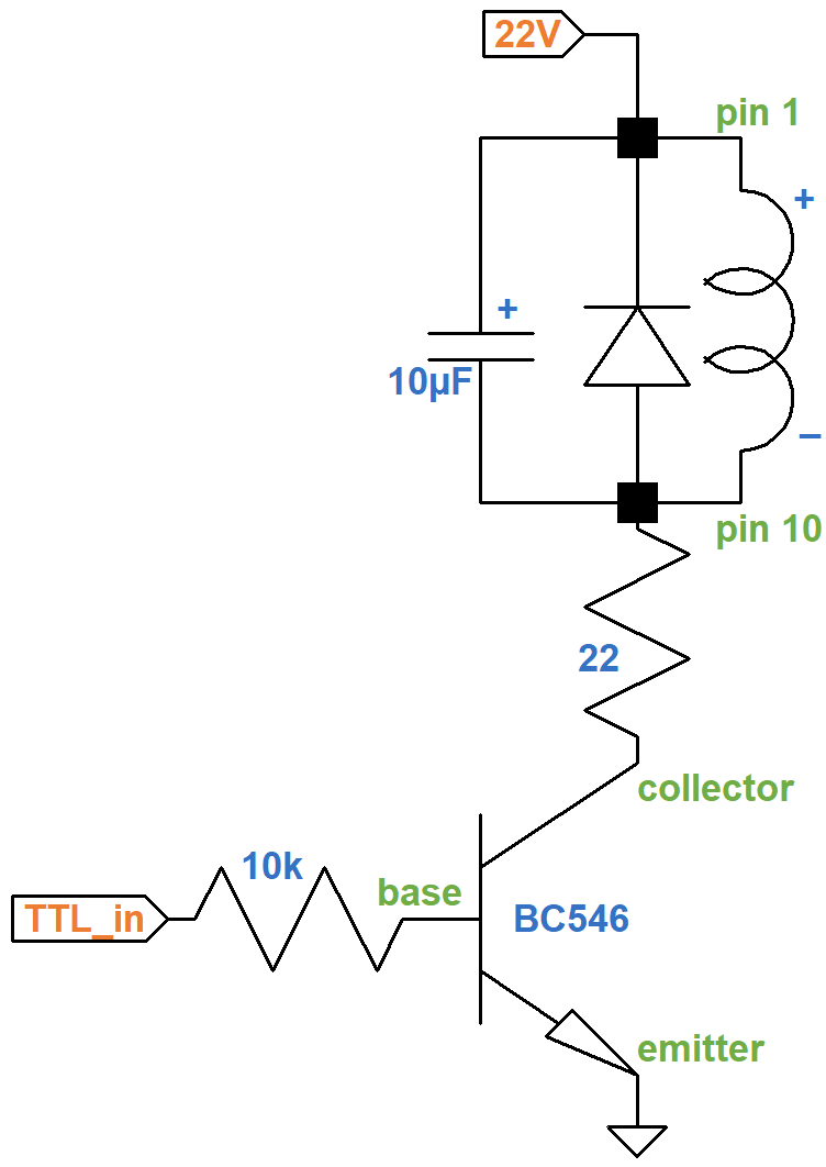
The Switchblade's microcontrollers live in a world of transistor-transistor logic (TTL), where 5V represents "on" and 0V represents "off." A 5V TTL signal cannot drive a 24V relay coil directly. Even if a 5V relay is used instead, TTL circuits are incapable of driving the relatively heavy current required. For these reasons, a BC546 transistor is used as the interface between TTL signals and the relay coil.
The transistor works like a vacuum tube, but with a twist: a current exercises control instead of a voltage. With an EF86 pentode, for example, when the plate-to-cathode voltage is greater than about 50V, it has very little effect on plate current. Grid voltage is almost in complete control.1 This is depicted in the plate characteristics by curves that are almost horizontal, each curve representing a different grid voltage.
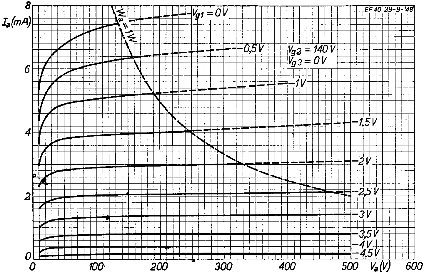
With a BC546 bipolar junction transistor, when the collector-to-emitter voltage is greater than about 2V, it has very little effect on collector current. Base current is almost in complete control. This is depicted in the collector characteristics by curves that are almost horizontal, each curve representing a different base current.
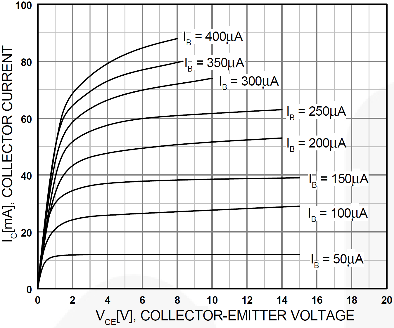
Like a silicon diode, the base-to-emitter voltage VBE needs to be at least 0.7V for current to flow. When the TTL input is at 0V, the transistor is in cutoff, the collector current IC = 0mA, the collector-to-emitter voltage VCE = 22V, and the voltage across the coil and 22Ω resistor is zero. The relay is deenergized. This point is just beyond the lower right corner of the collector characteristics shown here.
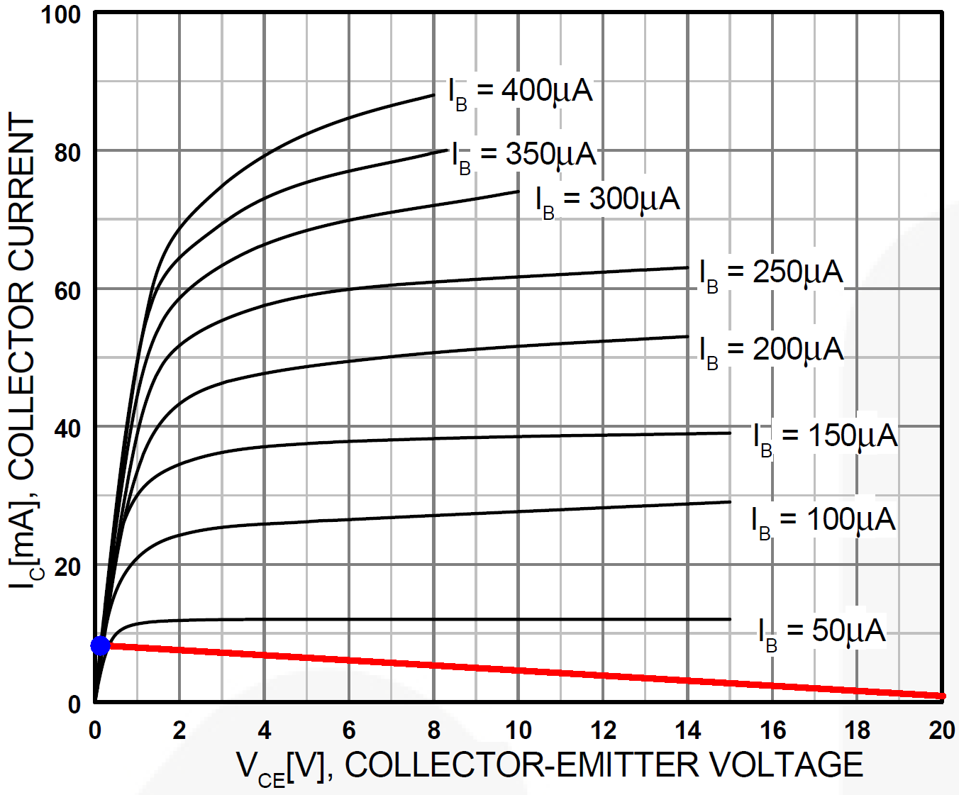
If VCE = 0, then there is 22V across the coil and 22Ω resistor. According to Ohm's Law, the collector current is
IC = 22V / (2.88kΩ + 22Ω) = 7.6mA
This is the upper left endpoint of the red load line. If VCE = 20V, the highest voltage on the X axis, then there is only 2V across the coil and resistor so the collector current is
IC = 2V / (2.88kΩ + 22Ω) = 0.7mA
This is the load line's endpoint on the lower right.
|
Guitar Amplifier Electronics: Circuit Simulation - know your design works by measuring performance at every point in the amplifier. |
When the transistor is turned on, it should be in saturation with VCE only slightly greater than 0V, as shown by the blue dot. This puts almost all of the 22VDC supply across the coil and 22Ω resistor. The lowest curve is for a base current of 50μA. It crosses the load line just barely to the right of the blue dot. The next curve for 100μA passes directly through the dot, so a base current of IB = 100μA is the minimum needed to put the transistor into saturation. The base current passes through the base resistor, which connects the TTL input to the base of the transistor. It limits current, just like the resistor in series with a light emitting diode (LED). When collector current flows, the base-to-emitter voltage is 0.7V, so to limit base current to 100μA for a 5V TTL signal, the base resistor value needs to be no greater than
(5V - 0.7V) / 100μA = 43kΩ
Hughes & Kettner uses 10kΩ, which allows 430μA of base current to flow, thereby ensuring that the transistor is well into saturation and the relay coil is fully energized.
In summary, a TTL signal of 0V creates no base current, turning the transistor off. No collector current flows and the collector-to-emitter voltage is 22V, leaving 0V for the relay coil, turning it off. A 5V TTL signal sends 430μA through the base of the transistor, creating a collector current of nearly 7.6mA and a collector-to-emitter voltage of nearly 0V. This puts 22V across the coil, turning the relay on.
References
1Richard Kuehnel, Guitar Amplifier Electronics: Basic Theory, (Seattle: Amp Books, 2018), pp. 45-47.