Leo Fender's Circuit Layout Strategy
"Those schematics were just so beautiful, man. It's all right there. And those Fender layout drawings that show where all the components go - had it not been for them, I probably would never have built my first amplifier." 1 - Mark Baier
Leo Fender never explicitly described his circuit layout strategy, but we have plenty of examples from which to draw conclusions. Let's apply some forensic science.
Bridging the Gap Between Circuit Design and Layout
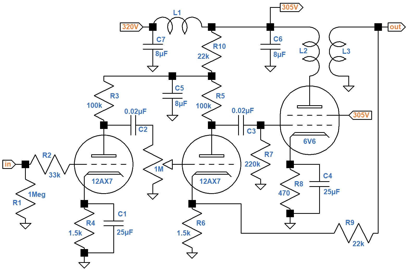
Here is a schematic of the Champ 5E1 drawn from a system design perspective.2
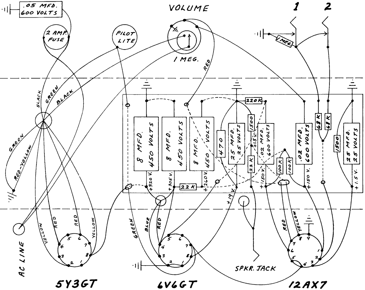
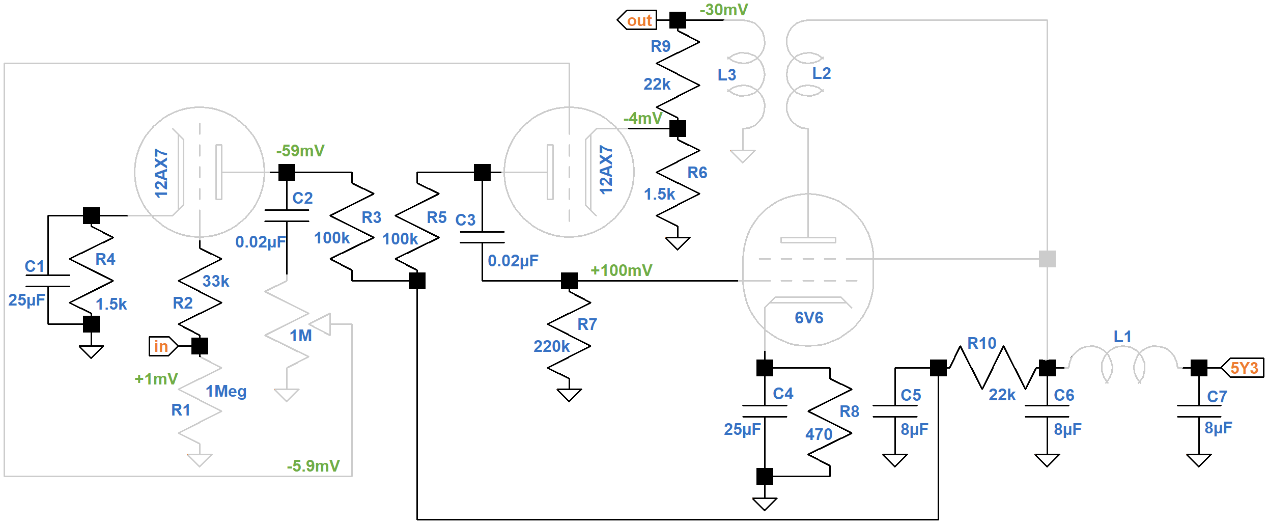
Circuit fabrication represents an entirely different perspective. Here is Leo's layout.

|
Guitar Amplifier Electronics: Fender Deluxe - from TV front to narrow panel to brownface to blackface Reverb |
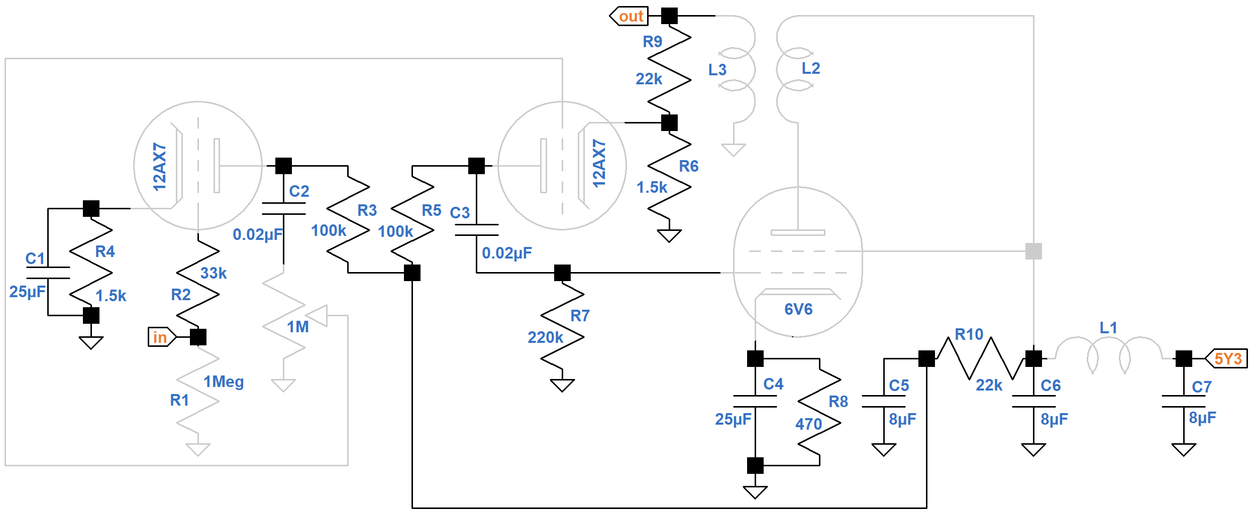
Let's bridge the gap between these two world views by incorporating some layout information into our schematic. Here the ordering of parts along the X axis of the schematic from left to right matches the ordering of parts on the circuit board from right to left. The vertical axis varies to make room for parts that are not on the circuit board, which are depicted in gray.
The input jack, R1, R2, and the first-stage triode form a straight line to the far left of the circuit. Only C1 and R4, which are at AC ground, are squeezed between the input and the chassis. To minimize feedback and noise in the most sensitive part of the amplifier, the input circuitry is the farthest from the power supply and the farthest from the power amp.
Lesson 1: Keep the guitar input circuit away from the power supply and power amp.
From left to right are the first stage, the second stage, and the power amp. The power supply works in the opposite direction, feeding the power tube first, then the upstream stages.
|
Guitar Amplifier Electronics: Basic Theory - master the basics of preamp, power amp, and power supply design. |
Keeping the parts for each stage close together keeps wires short. Wires are not perfect conductors. They have a small amount of resistance that increases with length and decreases with diameter. If they are wound into a coil they create inductance, but even a straight piece of wire or a component lead has some parasitic inductance caused by the magnetic field that it creates. The amount of inductance is directly proportional to lead length.
Two parallel metal plates have capacitance that depends on their surface area and separation. Wires, while not as capacitive as plates, also have capacitance that depends on their length and separation.
Inductance and capacitance in the wrong places can have severe effects at high frequencies, causing inaudible oscillation that can create havoc on the system. Keeping wires short reduces these parasitic effects.
Lesson 2: Arrange the circuit board linearly, stage by stage, from the first voltage amplifier to the power amp.
Signal Phase
For the first stage, the cathode circuit is placed first, the grid circuit second, and the plate circuit last. The second stage starts with the plate and ends with the cathode. To discover the reason, let's add some signal information to the circuit design schematic.
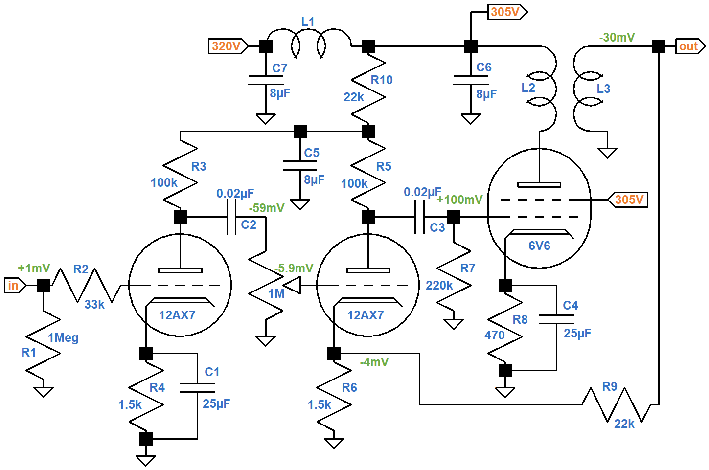
The first stage is an inverting voltage amplifier with a loaded voltage gain of 59, so if the guitar signal swings positive by 1 millivolt, the plate swings negative by 59 millivolts. These annotations are shown in green. With the volume control at 50-percent rotation (10-percent resistance for an audio taper), the grid of the next stage gets a -5.9mV swing. With negative feedback there is a +100mV swing at the 6V6 grid, which creates a -30mV swing at the 3.2Ω speaker. This creates a -4mV combination of feedback and cathode degeneration3 at the second-stage cathode.
|
Fundamentals of Guitar Amplifier System Design - design your amp using a structured, professional methodology. |
If we focus on phase, a logical layout pattern emerges.
Because of bypass capacitor C1, the cathode of the first stage is at AC ground. The next two circuits, are of opposite phase: +1mV versus -59mV. Any capacitive coupling between the circuits creates negative feedback. This is particularly true for very high frequencies like radio. Negative feedback reduces the chance of high-frequency oscillation.
The next circuit arrangement sees a similar flip flop: -59mV on one side and +100mV on the other. Next the phase reverses again: -30mV. The remaining circuitry is at AC ground. Upstream and downstream circuits that are in phase have the potential for creating positive feedback. If possible they should be separated by a layer of circuitry of opposite phase.
Lesson 3: Arrange the circuit board so that adjacent circuits are of oppositve phase.
Traditional voltage amplifiers facilitate this layout strategy because they are inverting. What about a non-inverting stage like the cathode follower that drives the famous Fender Bassman 5F6-A tone stack? Here is a schematic that incorporates layout information for the second-stage voltage amplifier, the DC-coupled cathode follower, and tone stack.
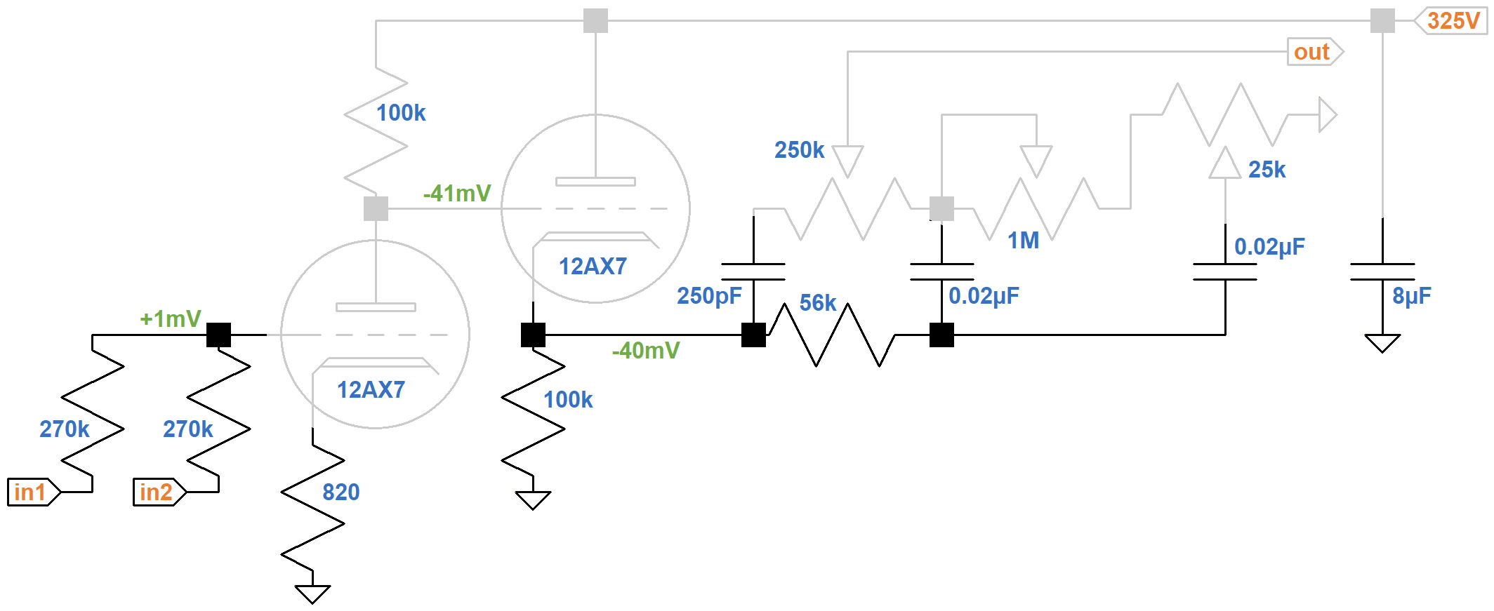
The triodes are contained within a single 12AX7 tube, so Fender takes the opportunity to reduce unnecessary wire lengths by connecting the 100kΩ plate load resistor directly at the socket from pin 1 (the first triode's plate) to pin 6 (the second triode's plate).
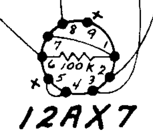
A short piece of wire connects pin 1 to pin 7, the second triode's grid, so all the connections at the top of the triodes are made at the tube socket.
Lesson 4: If you spot a wiring opportunity at the socket - take it!
The inverting voltage amplifier, with an unbypassed 820Ω cathode resistor, has a voltage gain of 41, so a +1mV swing at the grid creates a -41mV swing at the cathode follower's grid. The CF has slightly less than unity gain and is non-inverting, so we get -40mV at the stack input. The stack has three capacitors, so there are phase shifts, but overall the cathode follower and stack can be lumped together into a single circuit with the same phase and no amplification.
|
Guitar Amplifier Electronics: Circuit Simulation - know your design works by measuring performance at every point in the amplifier. |
Push-Pull
Because it has a single-ended power amp, the Champ has only unbalanced signals. From the guitar input jack to the speaker, the signal is represented by a voltage relative to ground. With a push-pull power amp, there are balanced signals represented by voltage differences. Consider, for example, the signal path from the Harvard 5F10's phase inverter to its output transformer primary.
Fender's layout keeps the two phases close together. Because they traverse the same path, noise and parasitically coupled voltages affect both phases equally. These common mode effects are ultimately rejected. A 10μV increase in voltage at one 6V6 grid, for example, cancels a 10μV increase at the opposite grid.
Lesson 5: Route balanced signals close together and in parallel.
Off-Board Resistors
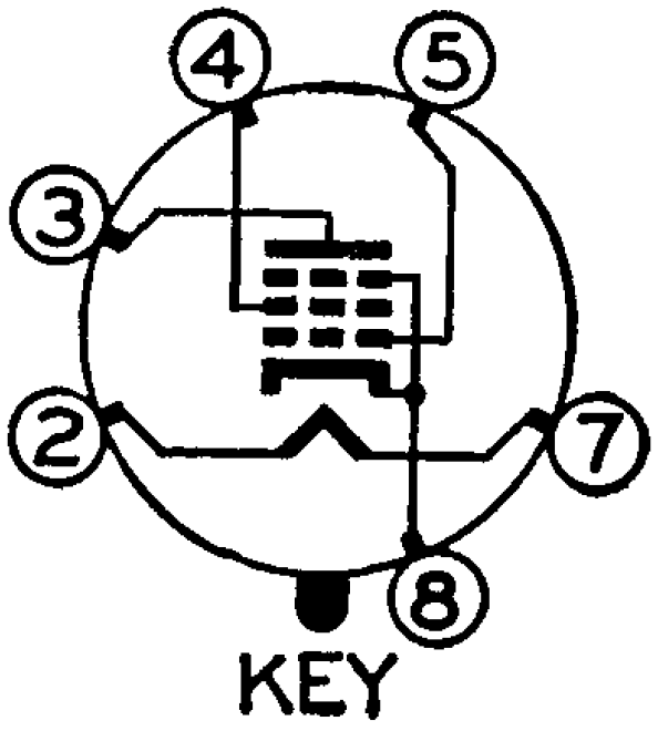
A 6V6 has no pin 6.
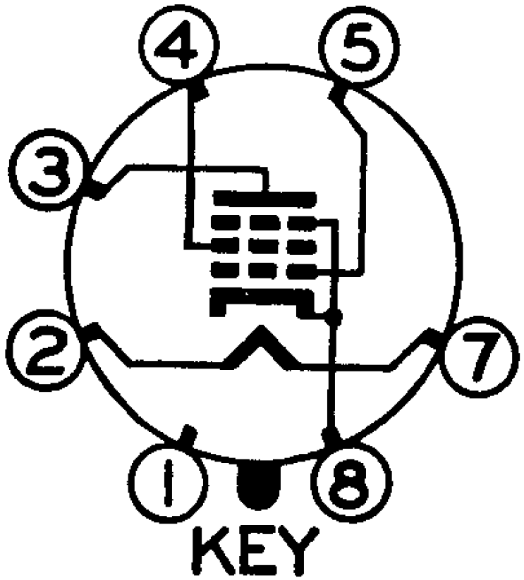
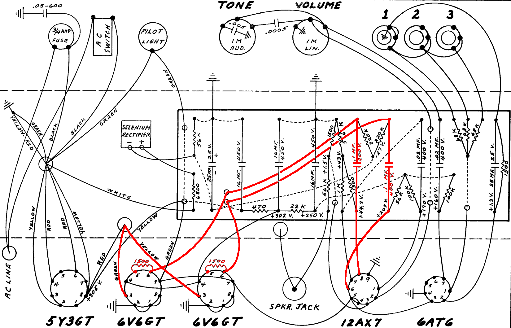
Nevertheless, the Harvard's balanced signal propagates over two parallel wires from the 0.1μF coupling capacitors to pin 6 of the 6V6 power tubes.
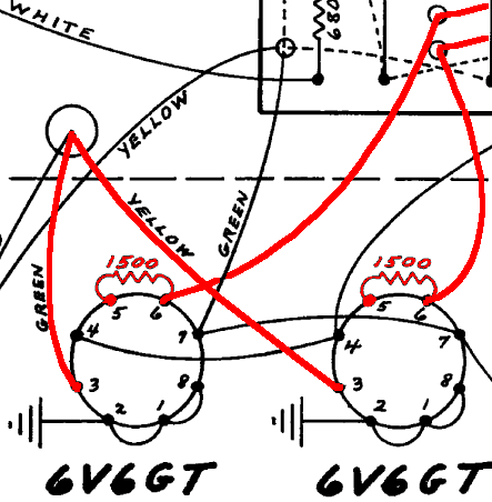
The socket's lug for pin 6 acts as a convenient mounting point for a 1.5kΩ grid-stopper resistor, enabling it to be connected directly to the 6V6 grid at pin 5. If the grid stopper is mounted to the circuit board, a wire is needed to connect it to the tube. A short wire minimizes inductance. Eliminating the wire entirely, as in the Harvard, eliminates parasitic inductance completely, thereby eliminating the chance of parasitic oscillation.
For the Twin Reverb AA270, Fender applies the same technique to 470Ω screen resistors by utilizing the unused pin 1 of each 6L6 power tube.
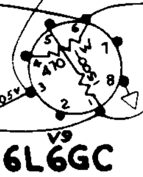
Lesson 6: Mount power tube grid stoppers and screen resistors directly to the socket.
The resistor and the tube's electrodes act as an RC low-pass filter to eliminate radio frequencies. Mounting the resistor close to the electrodes eliminates parasitic inductance between the resistance and the capacitance.
References
1Tom Wheeler, The Soul of Tone, (Milwaukee: Hal Leonard, 2007), p. 148.
2Richard Kuehnel, Fundamentals of Guitar Amplifier System Design, (Seattle: Amp Books, 2019).
3Richard Kuehnel, Guitar Amplifier Electronics: Basic Theory, (Seattle: Amp Books, 2018), p. 61.