Magnatone Model MP3 Fixed Bias Preamp
The first stage of the Magnatone MP3 guitar amplifier adds a strange 220kΩ resistor between the 140V plate supply and the cathode.
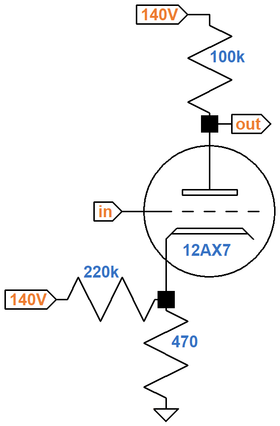
According to Magnatone's schematic, the measured cathode voltage is 0.5V. Let's see how this matches an average 12AX7 as documented by the data sheet.
According to Ohm's Law, if we assume the cathode voltage is 0.5V then the current through the 470Ω resistor is
0.5V / 470Ω = 1.06mA
The current through the 220kΩ resistor is
(140V - 0.5V) / 220kΩ = 0.63mA
The sum of this current and the plate current passes through the 470Ω resistor, so the plate current is
1.06mA - 0.63mA = 0.43mA
The plate-to-cathode voltage is equal to the plate supply voltage, minus the voltage drop across the 100kΩ plate load resistor, minus the cathode voltage:
140V - (0.43mA)(100kΩ) - 0.5V = 96.5V
Here on the 12AX7 plate characteristic curves, the point for 97V and 0.43mA is marked by the red dot, which indicates the grid voltage should be slightly less than -1V for this DC operating point.
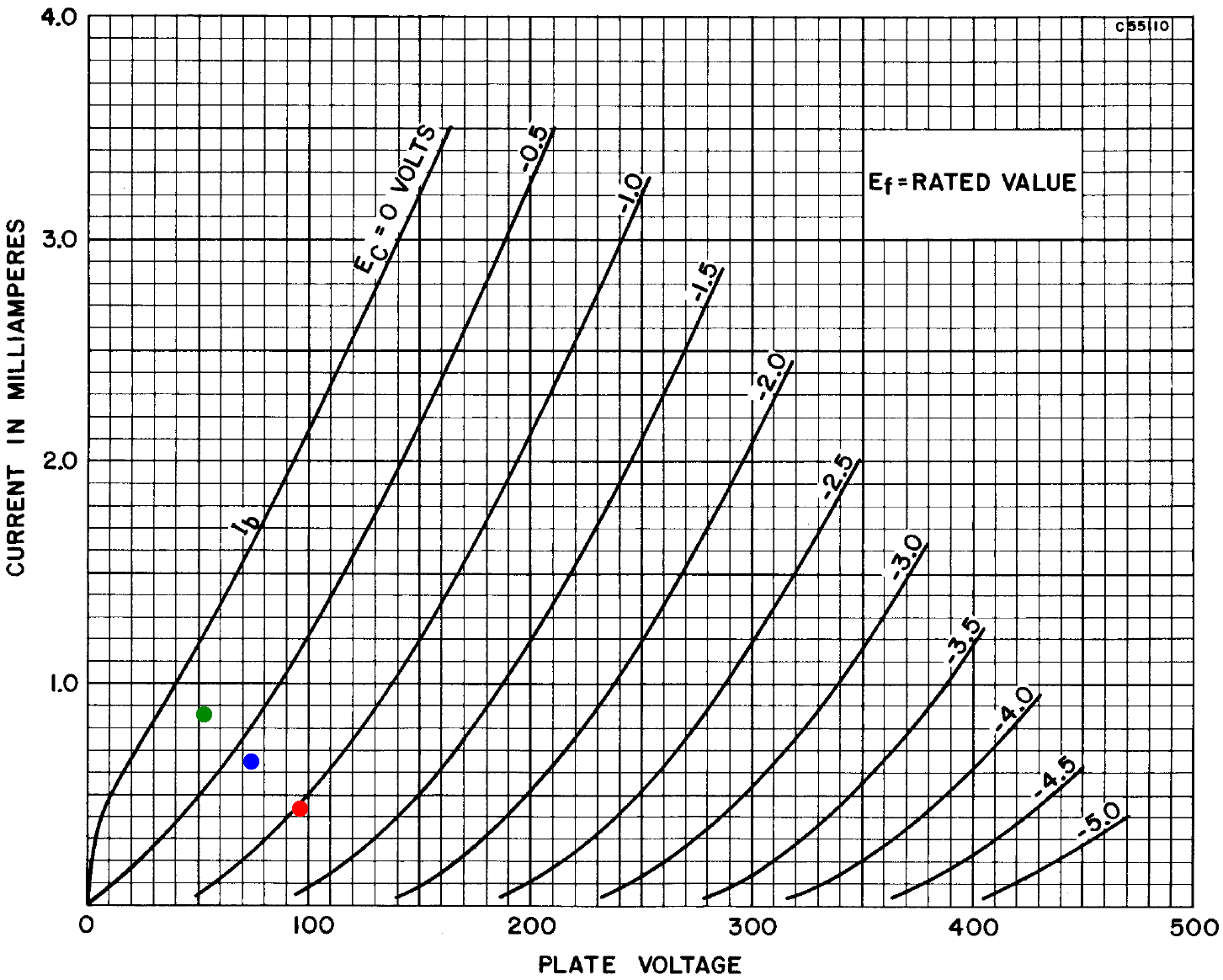
We can repeat these computations for an assumed 0.6V cathode (blue dot, 74V, 0.65mA) and an assumed 0.7V cathode (green dot, 53V, 0.86mA). The blue dot wins: it is in agreement with an imagined -0.6V curve.
|
Guitar Amplifier Electronics: Fender Deluxe - from TV front to narrow panel to brownface to blackface Reverb |
It is interesting to see that the dots form a line. In fact, the upper left endpoint of the line appears to be at a plate current of 1.4mA on the Y axis. The lower right endpoint is at a plate voltage of 140V on the X axis, so the dots are on a traditional DC load line,1 as shown by the red line of the 12AX7 calculator.
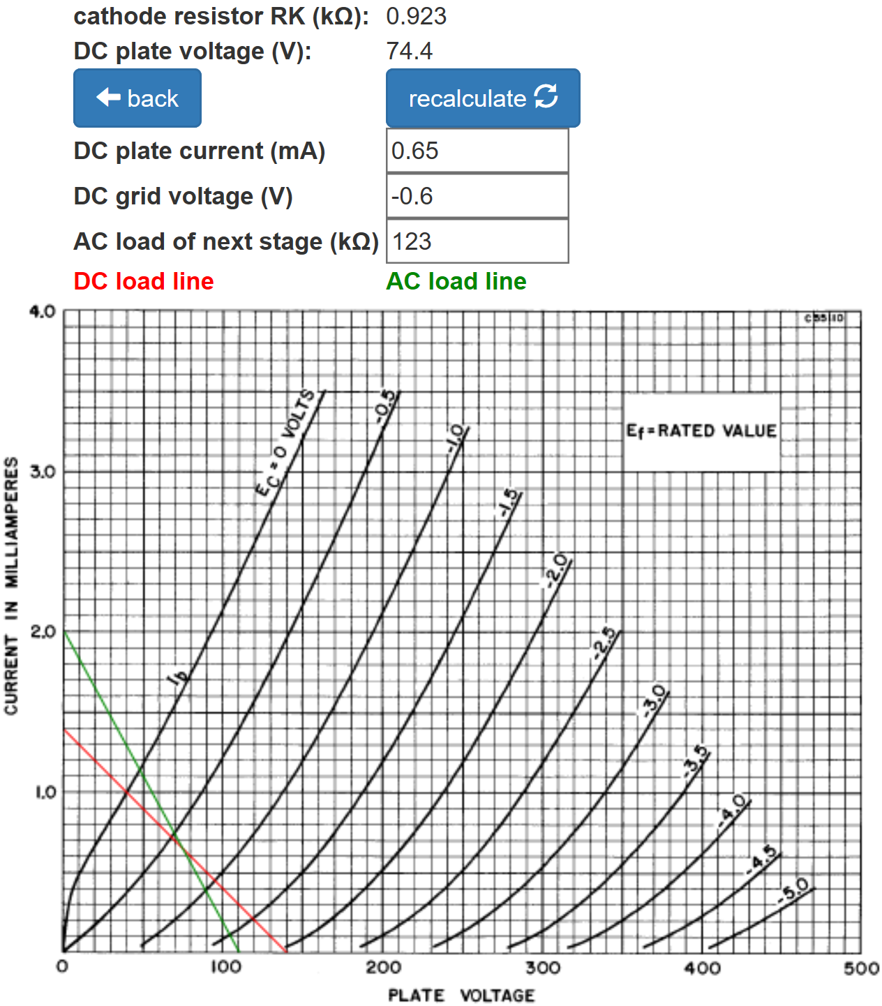
The calculator shows that the same bias can be achieved with a 923Ω cathode resistor for traditional cathode bias. This is not a standard resistor value, but great precision is not the hallmark of guitar amp design. For the discussion that follows, let's assume a circuit designer would select a 1kΩ value to achieve the same DC operating point using traditional cathode bias.
|
Guitar Amplifier Electronics: Basic Theory - master the basics of preamp, power amp, and power supply design. |
Fixed-Bias
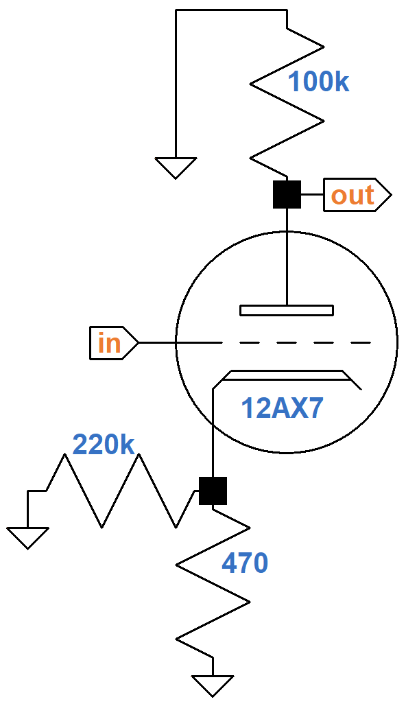
When the circuit is redrawn, Magnatone's concept becomes clear.
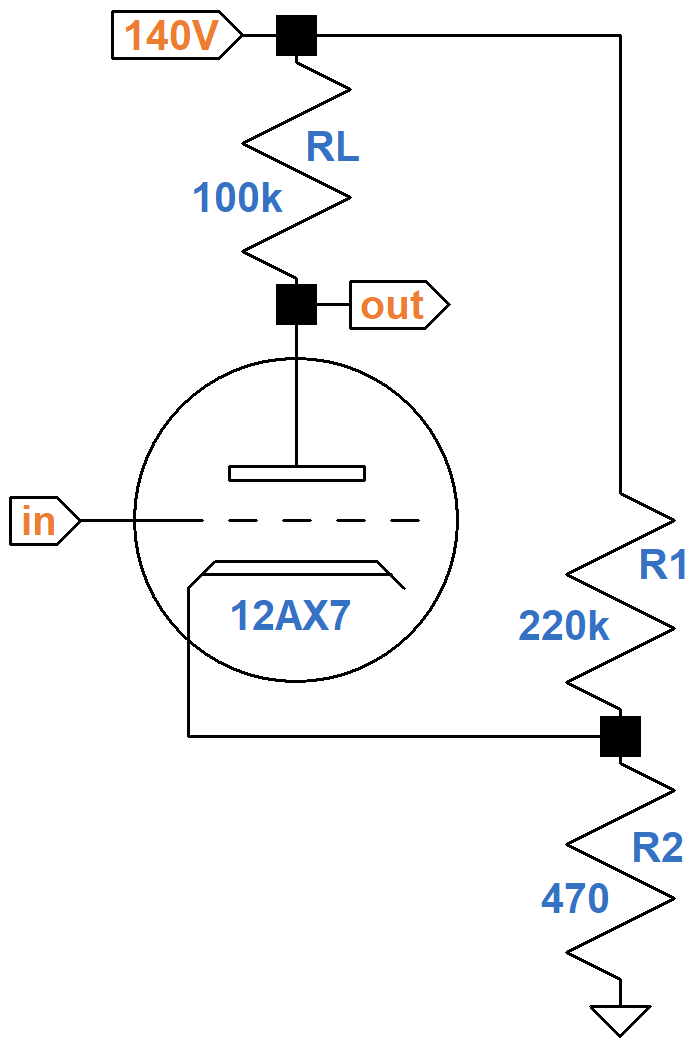
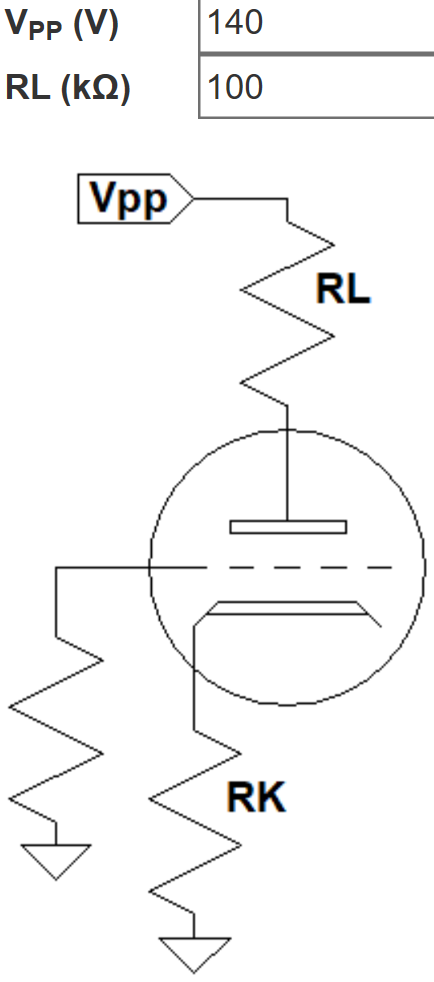
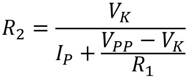
This is not a traditional cathode-biased preamp stage with an extra resistor. Instead, it is a pair of resistors that form a voltage divider to create fixed bias, as defined by the Radiotron Designer's Handbook.2 Here is a step-by-step procedure to determine the value of R2 for a fixed-bias voltage amplifier based on the plate supply voltage VPP, the plate load resistor RL, and the desired value of R1:
- Draw a traditional DC load line that connects the plate supply voltage VPP with VPP / RL.
- Along the load line, pick a desired DC operating point.
- Note the DC grid voltage VG and the DC plate current IP at that point.
- Solve for R2 using the following formula.
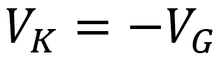
where the cathode voltage is
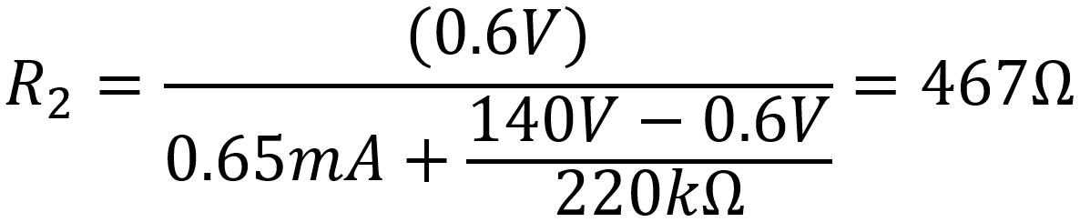
For a desired R1 = 220kΩ and VK = 0.6V, this procedure yields a result that is very close to Magnatone's value:
|
Fundamentals of Guitar Amplifier System Design - design your amp using a structured, professional methodology. |
From a DC perspective, does a pair of 220kΩ and 470Ω resistors for fixed bias offer any advantage over a traditional single-resistor design? Not really, unless you have a warehouse full of them and have 1kΩ resistors on backorder. We could also use 150kΩ for R1 and 390Ω for R2. In fact, there are many combinations of values for R1 and R2 that can be used to create the same DC operating point. So perhaps one advantage might be inventory flexibility. Typically, R1 has a large value to limit the current that the voltage divider draws from the high-voltage power supply.
Audio Performance
Here is Magnatone's first stage again, this time including the RC ripple filter for the 140V plate supply.
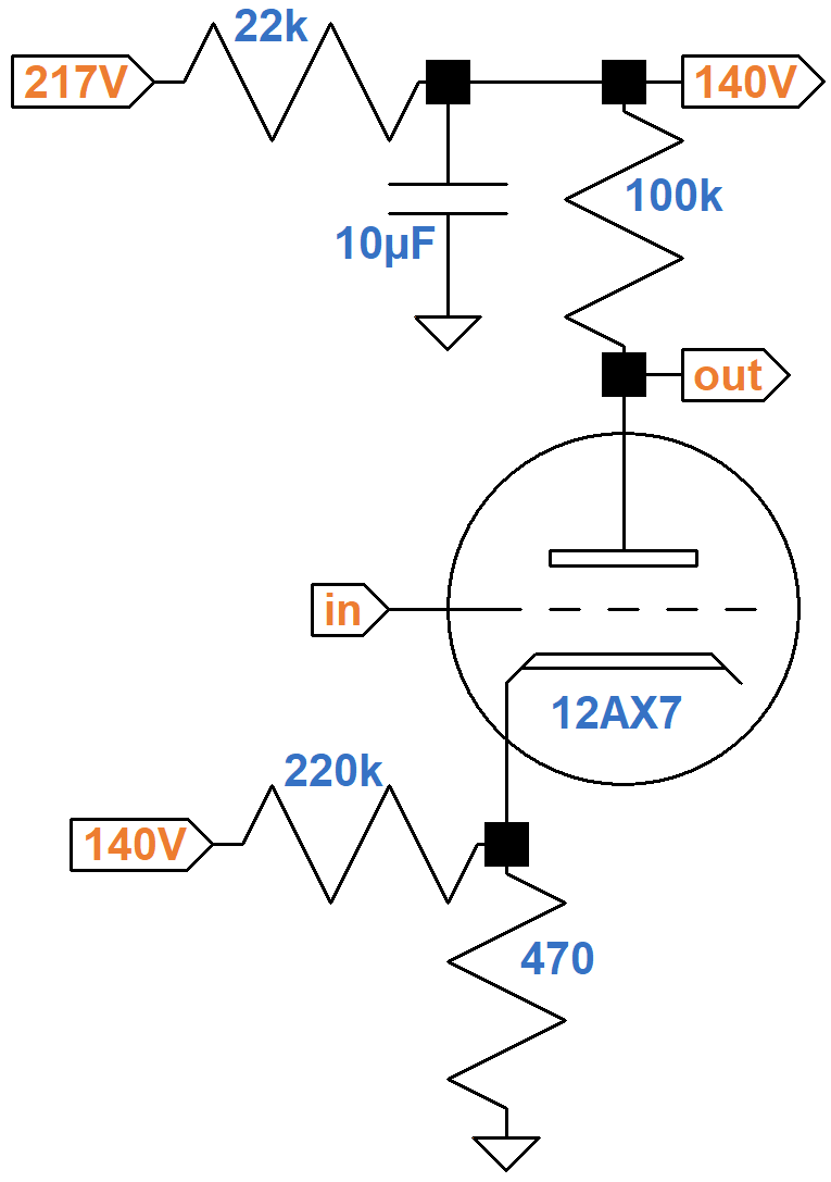
For audio signals, the capacitor acts as a short circuit,3 so the equivalent AC circuit puts the 220kΩ resistor in parallel with the cathode resistor.
220kΩ is huge compared to 470Ω, so the effective AC cathode resistor value is almost the same as without it: 469Ω. There is no significant difference in gain when the 220kΩ resistor is included, so audio performance is the same as for traditional cathode bias if a 470Ω resistor is used. To create the same DC operating point, however, we observed that cathode bias requires about 1kΩ.
|
Guitar Amplifier Electronics: Circuit Simulation - know your design works by measuring performance at every point in the amplifier. |
If the cathode is bypassed by a capacitor, then there is no negative feedback from cathode degeneration4 and audio performance is the same for either resistor value. In this case traditional cathode bias has the advantage that a smaller capacitor value can achieve full bypass. Magnatone's resistor is unbypassed, however, so gain is reduced. A 470Ω value, however, creates less cathode degeneration than a 1kΩ value. According to the Preamp Gain and Output Impedance calculator, the gain is 35.8dB when the cathode is fully bypassed. When unbypassed, gain is 33.6dB with 470Ω and 31.6dB with 1kΩ.
From a system design5 perspective, greater inventory flexibility and a few less dB attenuation when unbypassed are not particularly compelling reasons to add a resistor to the circuit. It is not surprising, therefore, that Magnatone's approach to establishing a DC grid bias is extremely rare in guitar amps. There is, however, a desirable side effect to this circuit: a discharge path for power supply filter capacitors that is independent of the vacuum tubes. When the amp is turned off, the voltage across the capacitors slowly bleeds away via the 220kΩ and 470Ω resistors.
References
1Richard Kuehnel, Guitar Amplifier Electronics: Basic Theory, (Seattle: Amp Books, 2018), p. 57.
2F. Langford-Smith, ed., Radiotron Designer's Handbook, 4th ed., (Harrison: RCA, 1953), p. 487.
3Richard Kuehnel, Guitar Amplifier Electronics: Basic Theory, (Seattle: Amp Books, 2018), pp. 19-21.
4Richard Kuehnel, Guitar Amplifier Electronics: Basic Theory, (Seattle: Amp Books, 2018), pp. 61-65.
5Richard Kuehnel, Fundamentals of Guitar Amplifier System Design, (Seattle: Amp Books, 2019).