Output Transformer Lumped-Element Model
Many characteristics of a transformer are distributed. There is capacitance between turns of a winding, for example, that is evenly distributed along the winding. A transformer model can be substantially simplified if the distributed capacitance is lumped into a single, ideal capacitor. Here is a lumped-element model of a real-world output transformer.1
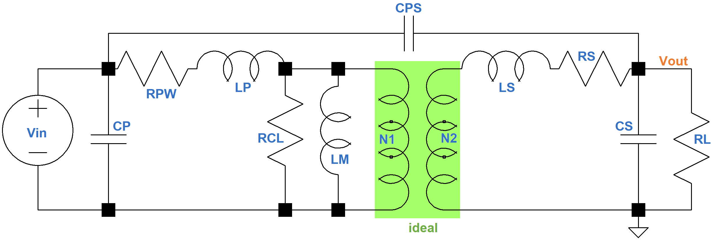
- CP = primary shunt and distributed capacitance
- LP = primary leakage inductance
- RPW = primary winding resistance
- RCL = resistance as a result of core (eddy current and hysteresis) losses
- LM = primary winding inductance
- CPS = primary-to-secondary inter-winding capacitance
- LS = secondary leakage inductance
- RS = secondary winding resistance
- CS = secondary shunt and distributed capacitance
- RL = load resistance across the secondary
- N1 = number of turns in the primary winding
- N2 = number of turns in the secondary winding
At the core of the model is an ideal transformer formed by N1 primary windings and N2 secondary windings.

|
Guitar Amplifier Electronics: Fender Deluxe - from TV front to narrow panel to brownface to blackface Reverb |
Midrange Transformer Losses
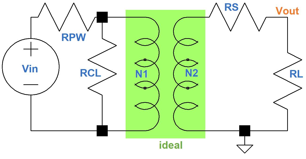
At midrange frequencies the large magnetizing inductance and the capacitances are open circuits and the small winding inductances are short circuits. This gives us just the pure resistances shown here.
To simply the notation, let's define n = N1/N2 to be the winding ratio, the number of turns in the primary divided by the number of turns in the secondary. The equivalent resistance at the ideal transformer primary, based on the secondary resistances, is
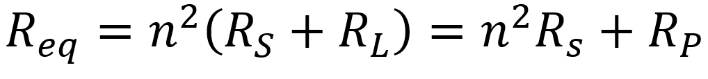
where RP is equal to RL translated from the secondary to the primary by an ideal transformer. This gives us, from the perspective of the primary circuit, this equivalent AC circuit, where VP = nVout and R1 = n2RS.
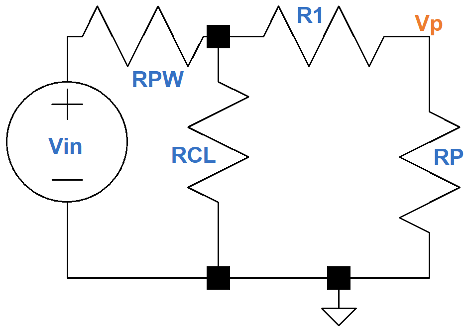
Notice that there are no inductances or capacitances in this circuit, only pure resistances. The output is in-phase with the input. If there are no transformer losses, then RPW = 0, R1 = 0, and RCL is infinite, corresponding to an open circuit. This means VP = Vin and the transformer output is
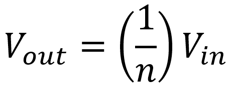
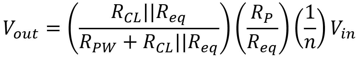
which is the relationship for an ideal transformer. For the lossy circuit, on the other hand, we get an attenuated output of
|
Guitar Amplifier Electronics: Basic Theory - master the basics of preamp, power amp, and power supply design. |
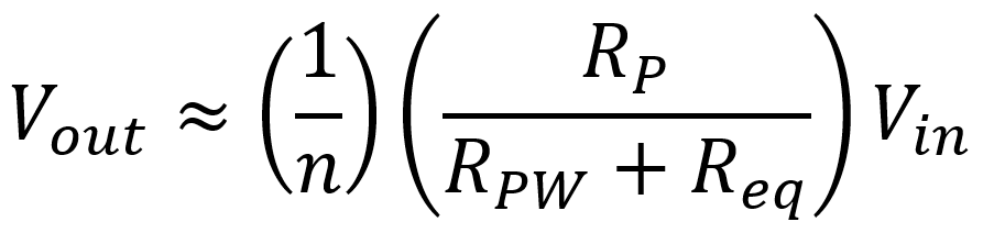
For audio transformers operating over midrange frequencies, the voltage losses due to winding resistance are more important than core losses, and current is relatively unaffected.2 This gives us this approximate circuit.
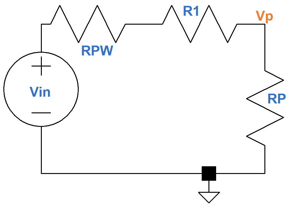
The output voltage is approximately
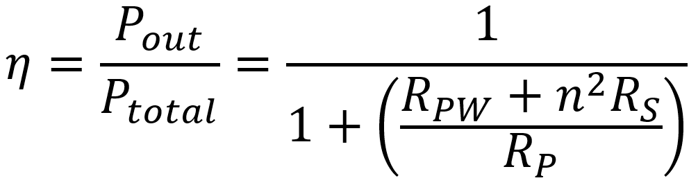
Manufacturers describe midrange losses in terms of efficiency and insertion loss. Transformer efficiency is defined as the output power Pout divided by the total power Ptotal, which includes losses. For the approximate audio circuit, we get a transformer efficiency of
|
Fundamentals of Guitar Amplifier System Design - design your amp using a structured, professional methodology. |
Consider, for example, the Amplimo BV Type 3A524 output transformer. According to its data sheet, RP = 3.545kΩ, RPW = 72.9Ω, RS = 0.423Ω, and n = 21.05. This gives us an estimated efficiency of 93 percent, which is excellent.
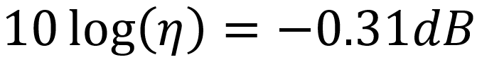
The insertion loss is the power loss induced into the circuit by the addition of the transformer. It is equal to the output power relative to the input power, measured in dB.3 For the 3A524, for example, we get
Low-Frequency Transformer Response
At low frequencies, the primary winding inductance LM is a significant factor, so the circuit looks more like this.
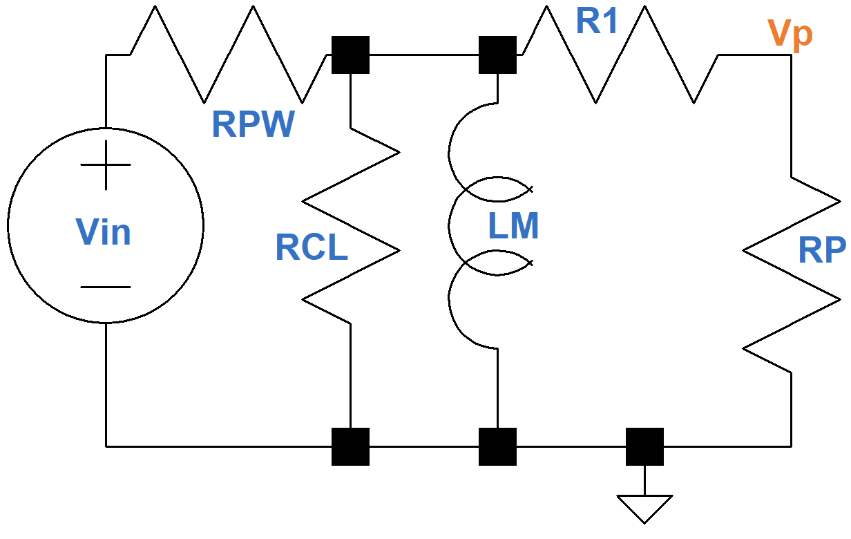
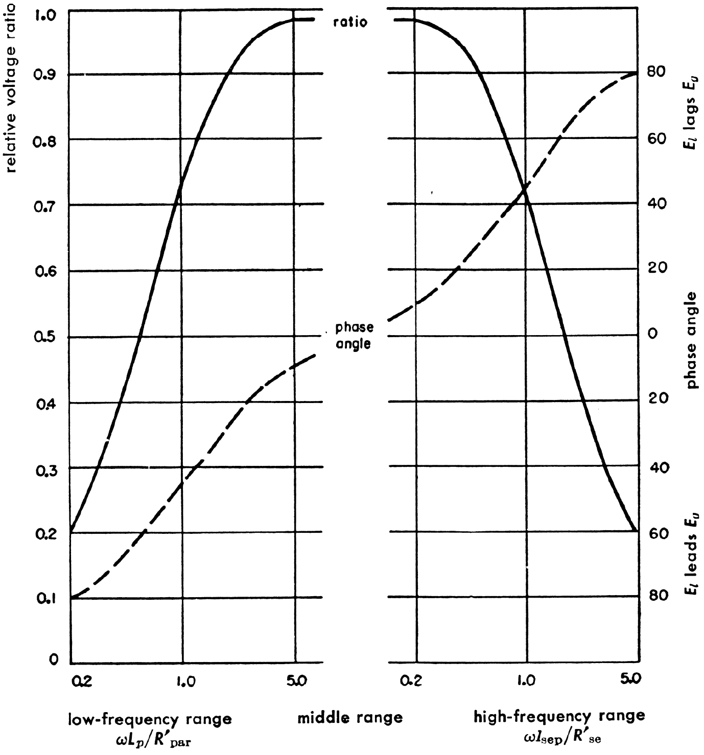
The inductance LM is very high, usually on the order of several hundred henries. Its reactance 2πfLM decreases when the frequency decreases, however, so eventually it begins to short out the resistances in parallel with it, attenuating the output signal. The voltage driving an inductor leads its current by 90 degrees, which creates the shift in phase angle shown here.4
|
Guitar Amplifier Electronics: Circuit Simulation - know your design works by measuring performance at every point in the amplifier. |
High-Frequency Transformer Response
At high frequencies, especially when the transformer is driven by pentodes or beam power tetrodes, things become more complicated. The midrange frequency circuit needs to be modified to include the total leakage inductance reflected in the primary and the equivalent winding shunt capacitance Ceq that are shown here, where L1 = LP + n2LS and R2 = RPW + n2RS.
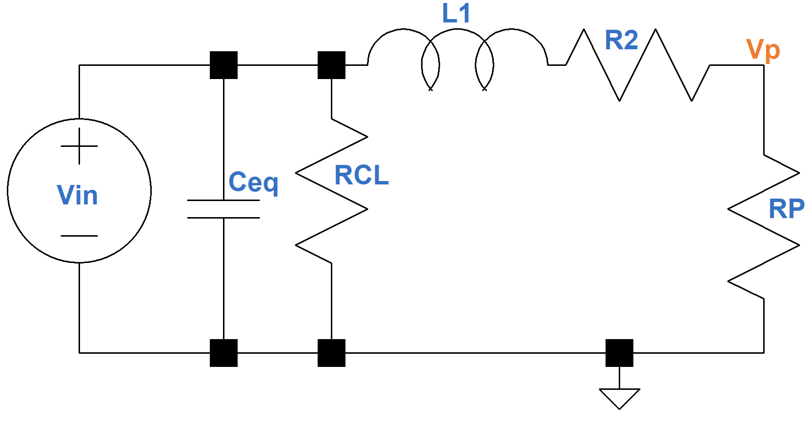
The resistance due to core losses RCL comes from eddy currents and hysteresis and is about as large as the plate resistance of a pentode or beam power tetrode. The inductance and capacitance in the circuit cause increasing attenuation with increasing frequency. The voltage in a capacitor lags the current through it by 90 degrees, so when combined with the effects of the leakage inductance we get the opposite phase angle effect that we observed at low frequencies.
References
1F. Langford-Smith, ed., Radiotron Designer's Handbook, 4th ed., (Harrison: RCA, 1953), p. 204.
2F. Langford-Smith, ed., Radiotron Designer's Handbook, 4th ed., (Harrison: RCA, 1953), p. 206.
3Edward C. Jordan, ed., Reference Data for Engineers: Radio, Electronics, Computer, and Communications, 7th ed., (Indianapolis: Howard W. Sams, 1985), pp. 13-14.
4Reference Data for Radio Engineers, 3rd ed., (New York: Federal Telephone and Radio Company, 1949), p. 198.