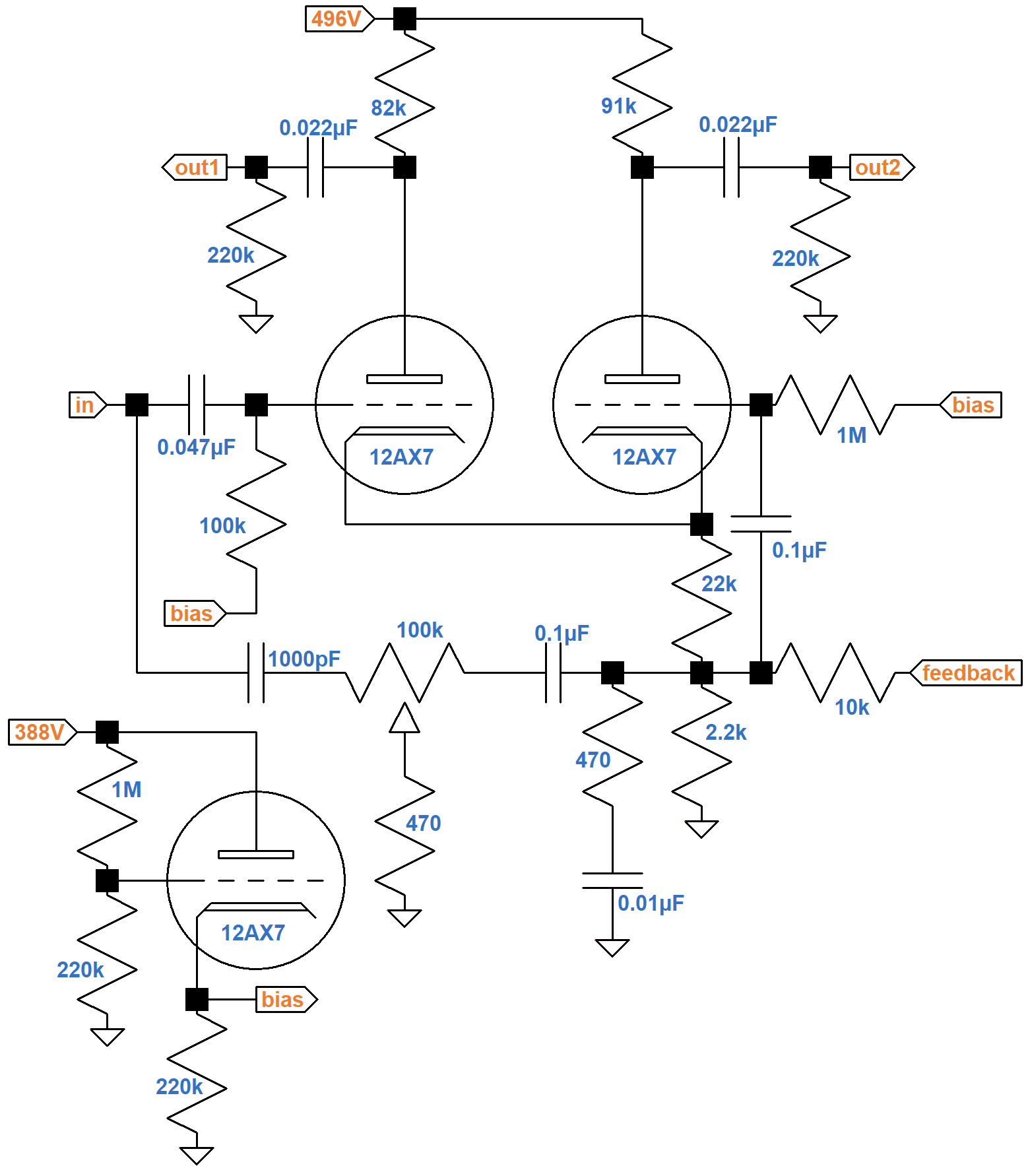
Hiwatt Fixed-Bias Phase Inverter
Many Hiwatt guitar amplifiers use a cathode follower to create a fixed bias for the phase inverter.
"The magic part of the Hiwatt, and [the reason] it will produce such a powerfully clean sound, is its phase inverter. It has a bias on the grid. That bias prevents the phase inverter from shifting upward or downward, as does a typical Fender or Marshall, which gives rise to early distortion." 1 - Victor Mason, Mojave Ampworks
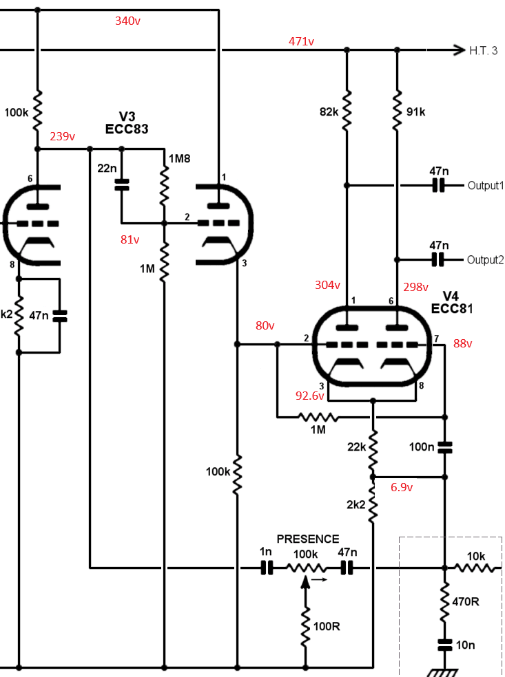
The circuit shown and the calculations that follow are circa 1983, for which an ECC83/12AX7 is substituted for the original ECC81/12AT7. For a 1971 version, Hiwatt historian Mark Huss measures the voltages shown here.2
The DC Circuit
Under DC conditions, all capacitors are open circuits, which simplifies the schematic considerably.
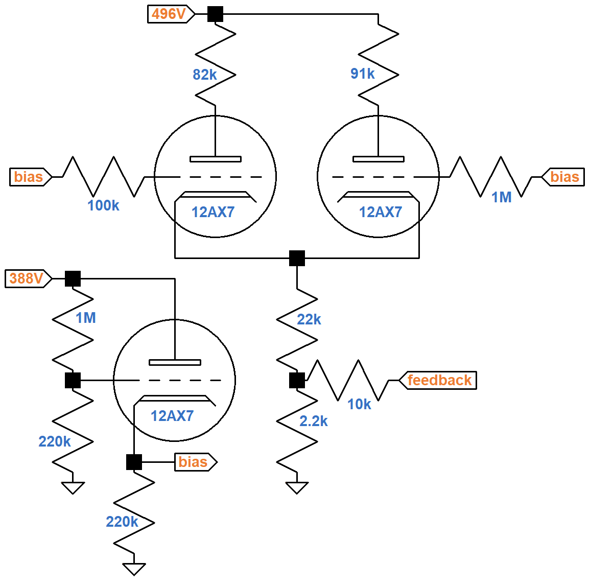
The plate supply voltages were measured by Mark Huss.3 Assuming the cathode follower's grid does not draw current, its voltage relative to ground is
(388V)(220kΩ) / (220kΩ + 1MΩ) = 70V.

|
Guitar Amplifier Electronics: Fender Deluxe - from TV front to narrow panel to brownface to blackface Reverb |
There is no resistance between the plate and the plate supply, but 220kΩ lies between the cathode and ground. The red load line shown here connects the 388V plate supply voltage (lower right endpoint) with 388V / 220kΩ = 1.76mA (upper left endpoint).
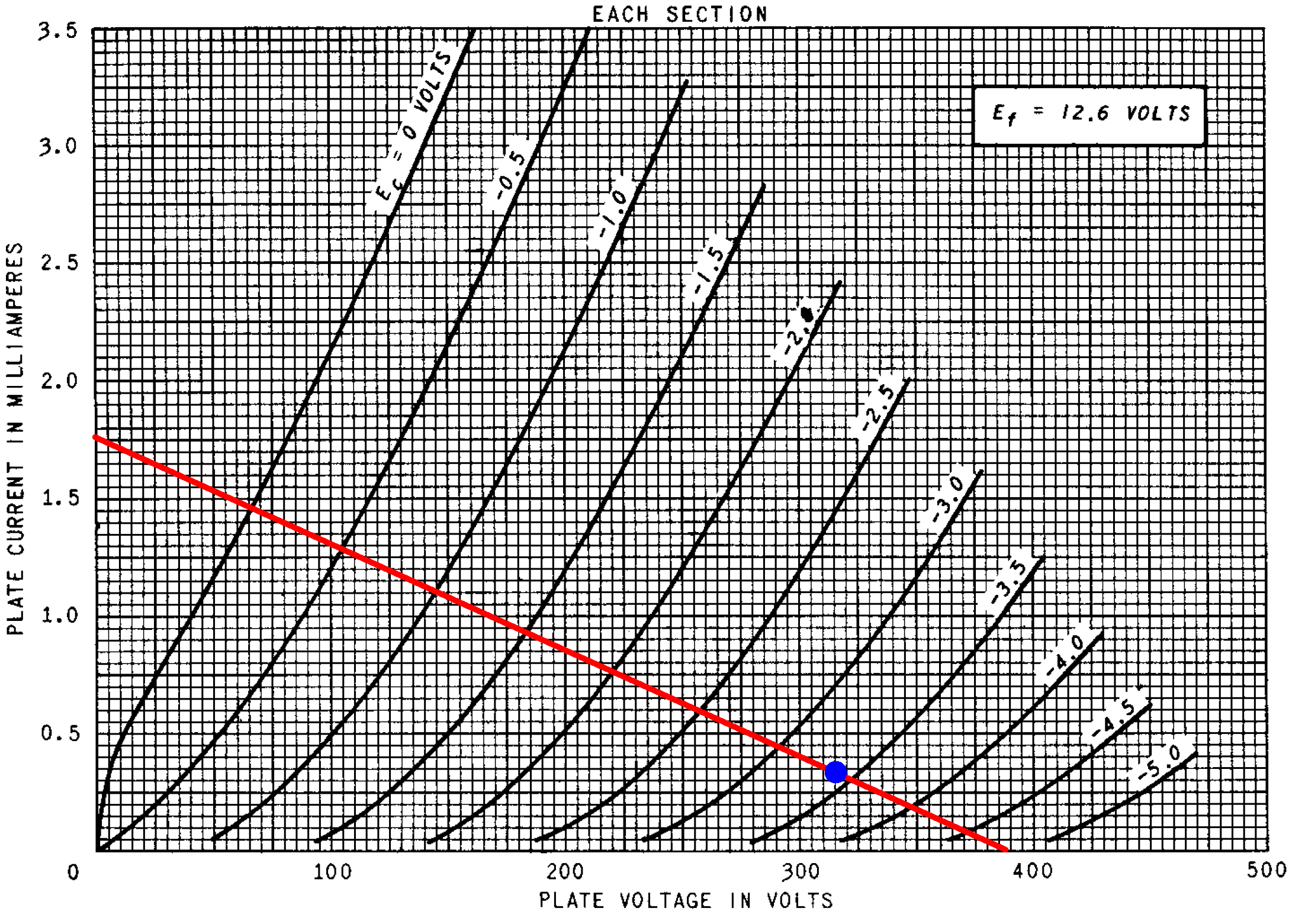
The blue dot marks an estimated DC operating point for an average 12AX7 and ideal components. The grid-to-cathode voltage is -3.4V. The cathode-to-ground is therefore 73.4V and the plate current (Y axis) is
73.4V / 220kΩ = 0.33mA
The plate-to-cathode voltage (X axis) is
388V - 73V = 315V
The 73V output sets the DC voltage at the grids of the triodes forming the long-tailed-pair phase inverter. According to the Cathode Follower calculator, with a 220kΩ cathode resistor the output impedance is only 617Ω.
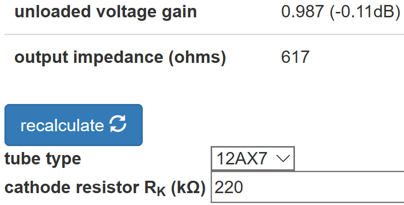
The cathode follower therefore acts as a well-regulated voltage source to create a fixed DC grid bias for the LTP.
|
Guitar Amplifier Electronics: Basic Theory - master the basics of preamp, power amp, and power supply design. |
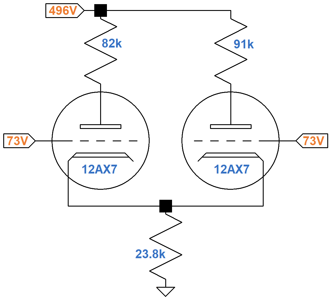
Assuming the LTP grids draw no current, the voltages across the 100kΩ and 1MΩ resistors connected to them are zero, so the grids are at 73V. The 16Ω tap of the output transformer secondary has negligible DC resistance, so it is at DC ground, placing the 10kΩ feedback resistor in parallel with the 2.2kΩ tail resistor for an effective resistance of 1.8kΩ. This is in series with the 22kΩ cathode resistor RK2 for an effective resistance of 23.8kΩ between the cathodes and ground. This circuit therefore creates the same DC operating points for the triodes.
The 23.8kΩ tail resistance carries the DC plate current of two tubes, so if we double its value to 47.6kΩ and use an average plate load resistor value of 87kΩ, an equivalent DC circuit for one triode looks like this.
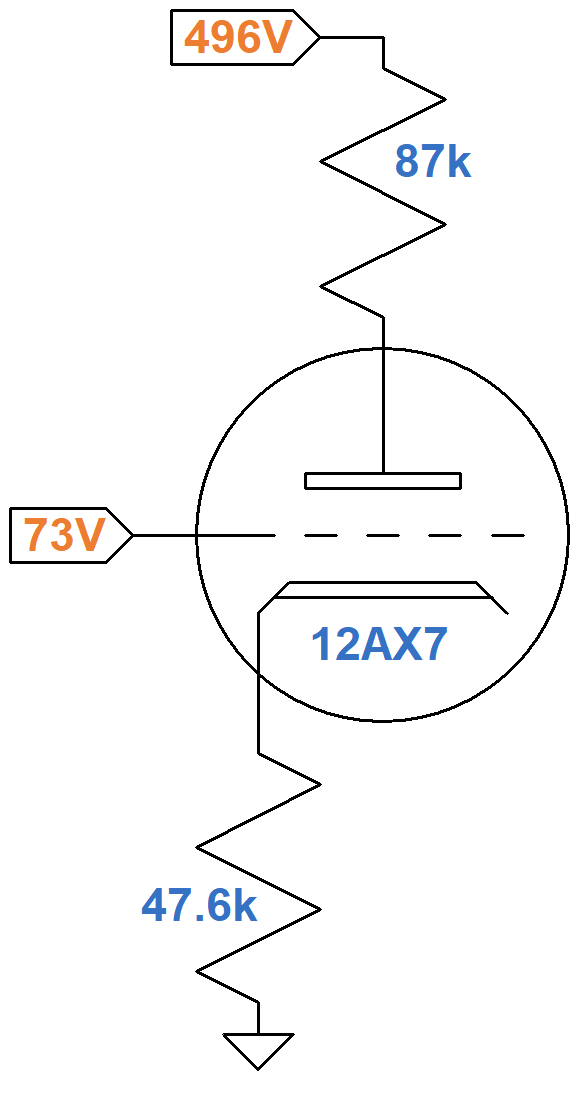
According to Ohm's Law, if it were possible for the plate-to-cathode voltage to be 100V, then the plate current would be
(496V - 100V) / (87k + 48k) = 2.93mA
The upper-left endpoint on the red DC load line shown below represents 100V, 2.93mA. The endpoint at the lower right is the 496V plate supply voltage and zero plate current.
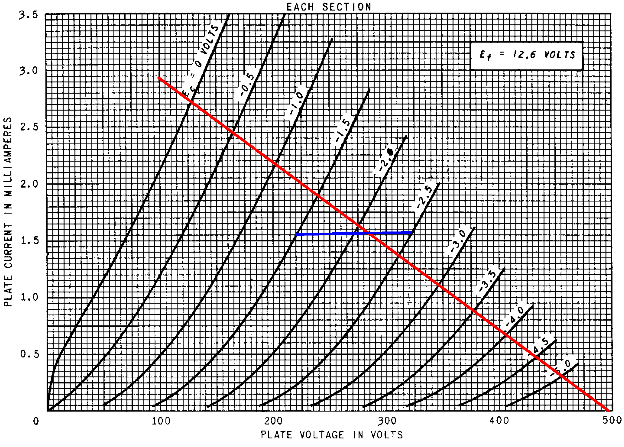
Let's explore 3 different possible values for the LTP DC grid bias. For a 73V grid-to-ground voltage, if the grid-to-cathode voltage is -1.5V, then the cathode voltage is 74.5V and the plate current is
74.5V / 48kΩ = 1.55mA
If the grid-to-cathode voltage is -2V, then the cathode voltage is 75V and the plate current is
75V / 48kΩ = 1.56mA
If the grid-to-cathode voltage is -2.5V, then the cathode voltage is 75.5V and the plate current is
75.5V / 48kΩ = 1.57mA
These points are joined by the two blue line segments shown. They appear to intersect the load line at a DC grid-to-cathode voltage of -2.1V, a DC plate current of 1.56mA, and a plate-to-cathode voltage of 285V.
|
Fundamentals of Guitar Amplifier System Design - design your amp using a structured, professional methodology. |
Negative Feedback - Bass Frequencies
At 100Hz, the reactance of a 0.1μF capacitor is 16kΩ. For smaller capacitors it is proportionately higher. A 0.01μF capacitor, for example, has a reactance of 160kΩ at 100Hz. Based on these values, for bass frequencies the presence control circuit and the tone-shaping circuit at the LTP cathodes can be removed without affecting the AC response. The cathode follower, which provides 73VDC, has a very low output impedance, so its output is essentially grounded for AC signals.
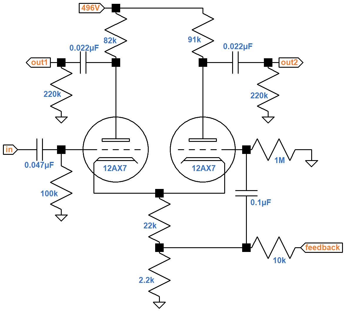
According to the Preamp Gain and Output Impedance calculator, a traditional 12AX7 voltage amplification stage has an unloaded voltage gain of 58 (35dB) for an average plate load resistor value of 87kΩ and a fully bypassed cathode resistor. For an LTP we expect about half: 29. This is the unloaded voltage gain from LTP input to LTP output without negative feedback.
The LTP drives an AC load of 220kΩ created by each power amp grid-leak resistor. It has an output impedance of about 36kΩ, so when loaded, gain is reduced by a factor of
220kΩ / (220kΩ + 36kΩ) = 0.86
Loaded voltage gain from LTP input to LTP output is therefore
(0.86)(29) = 25 (28dB)
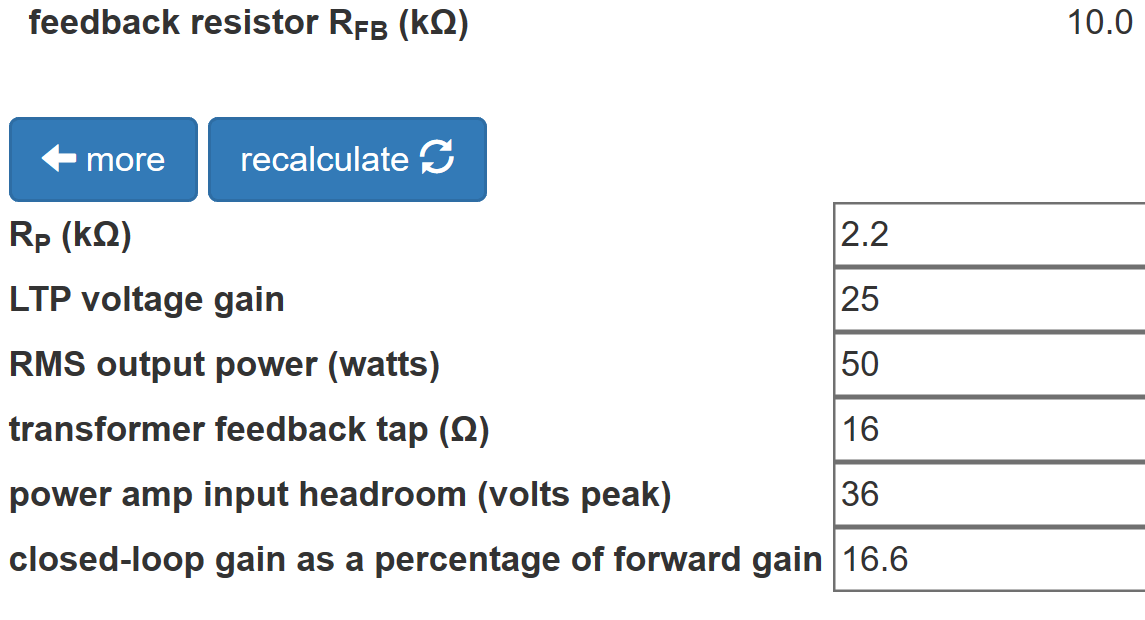
Let's assume the power amp creates 50W RMS at the speaker and that its EL34 power tubes are biased at -36V. According to the LTP Negative Feedback calculator, a 10kΩ feedback resistor from the 16Ω secondary tap creates a closed-loop gain that is 17 percent of the open-loop gain.
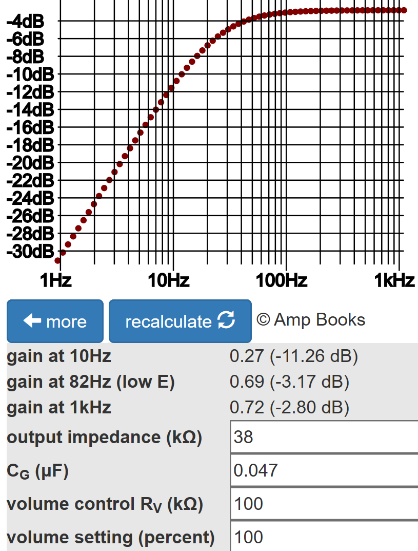
Negative feedback therefore decreases gain, measured from the LTP input grid to the speaker, by 15dB for bass frequencies.
According to the Coupling Capacitor calculator, there is very little bass attenuation created by the 0.047μF coupling capacitor value at the LTP front end.
|
Guitar Amplifier Electronics: Circuit Simulation - know your design works by measuring performance at every point in the amplifier. |
Negative Feedback - Treble Frequencies
At treble frequencies, the presence circuit and some additional tone-shaping circuitry come into play.
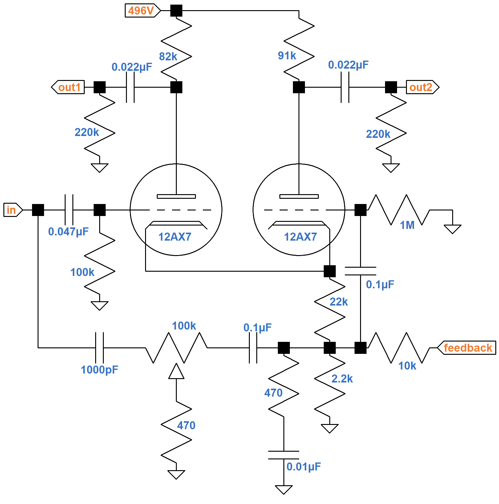
When the wiper swings to the left (control fully counterclockwise), there is 100kΩ between it and the feedback network, which has much lower impedances, so the 470Ω resistor connected to the wiper has no effect on feedback. The resistor combines with the 1000pF capacitor to its left, on the other hand, to form a low-pass filter that attenuates treble.
With the wiper fully to the right, the 100kΩ between the capacitor and the wiper eliminates this treble cut. The 470Ω resistor now forms a low-pass filter with the 0.1μF capacitor to its right, which attenuates high-frequencies for the negative feedback signal. This creates treble boost. The Hiwatt presence control can therefore create both treble cut and treble boost, depending on the control position.
To the right of the presence control is a 470Ω resistor and a 0.01μF capacitor in series. They form a shunt impedance for a fixed low-pass filter for the feedback signal, thereby reducing negative feedback for high frequencies. This fixed treble boost combines with the presence control's variable treble boost to create the control dynamics that Hiwatt founder Dave Reeves wanted to achieve.
References
1Dave Hunter, Amped, (Minneapolis: Voyageur Press, 2012), p. 153.
2Personal correspondence with Mark Huss, October 2022.
3Mark Huss, "My DR504OL." Available at https://hiwatt.org/tech2.html (Accessed April 9, 2020)
4Richard Kuehnel, Guitar Amplifier Electronics: Basic Theory, (Seattle: Amp Books, 2018), pp. 142-153.