Park Vintage 20 LE Guitar Amplifier Negative Feedback
"Also worthy of note was the Park Vintage 20 LE (model 1231), which was a valve combo featuring a pair each of EL84s and ECC83s powering a single 30-watt Celestion 12" speaker, and whose design origins went back to the old Marshall 20-watt heads. It looked terrific with its rounded, angle-front cabinet design finished in brown vinyl, but the sound as I recall wasn't quite as good as its looks, and it certainly wasn't on the market for very long. However, once the old stock of parts was used up, it was slightly redesigned around new transformers and re-released in 1980 as model 1273, with I'm sure an appropriate improvement in sound quality." 1 -Michael Doyle
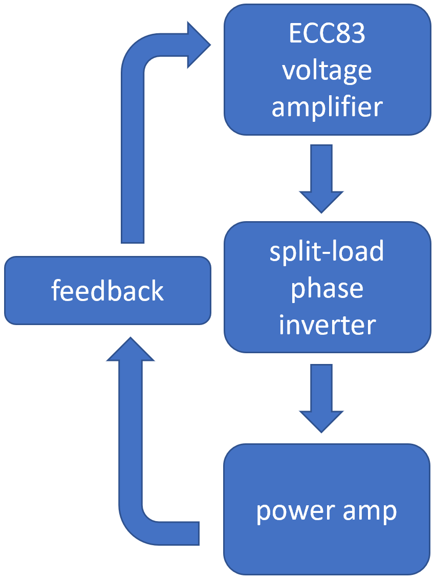
Unlike single-ended amps like the Fender Champ or push-pull amps like a Marshall JMP50, Park models 1231 and 1273 have global negative feedback that extends across three stages.
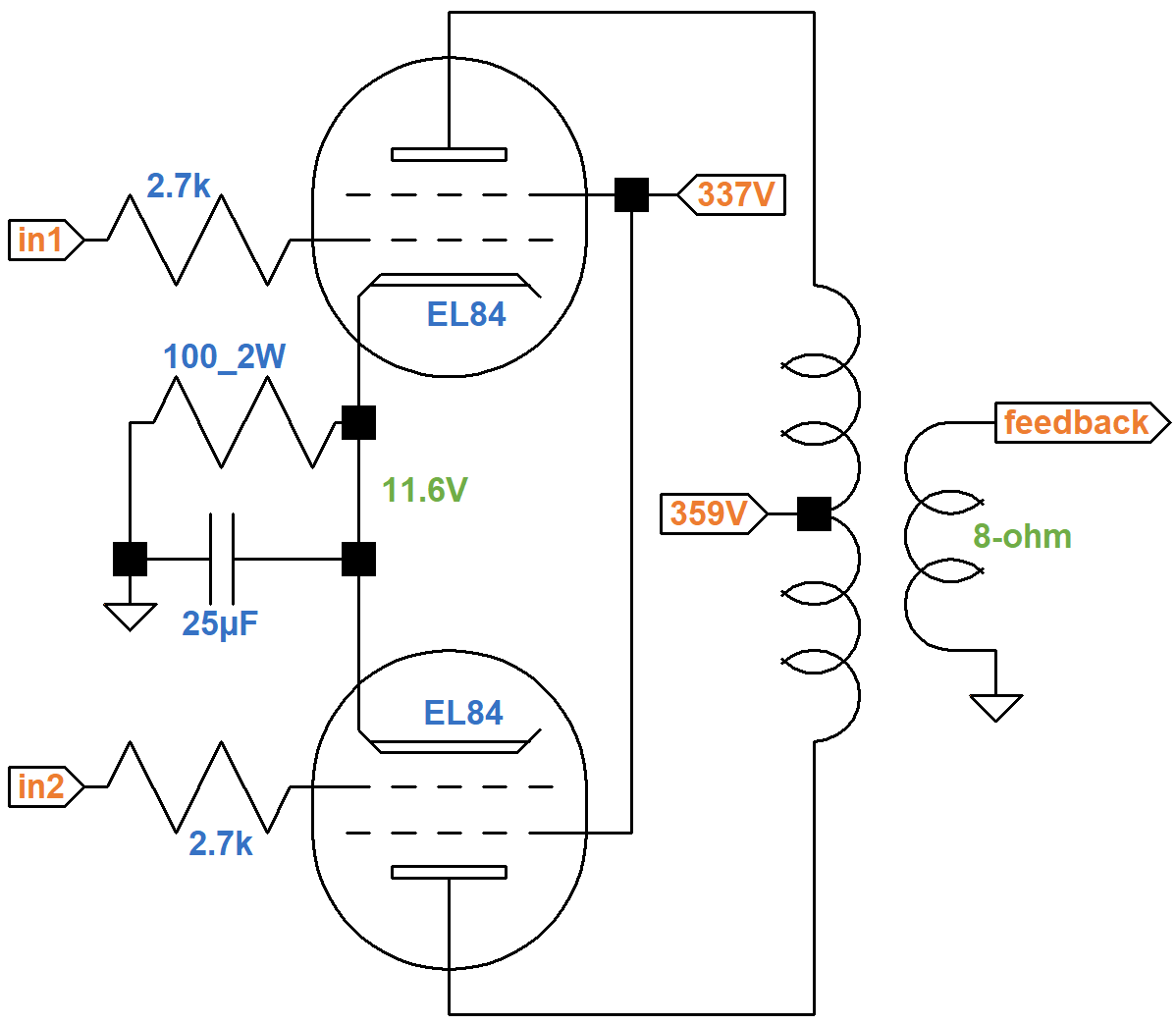
The power amp has a pair of EL84 power pentodes that are cathode biased at -11.6V.

|
Guitar Amplifier Electronics: Fender Deluxe - from TV front to narrow panel to brownface to blackface Reverb |
Feedback comes from the 8Ω tap of the output transformer secondary. To produce 20 watts RMS, the full-power output voltage is
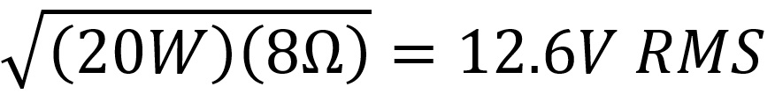
At full power the signal level at the EL84 grids is 11.6V peak. To get the RMS value we divide by the square root of 2:
11.6V / 1.414 = 8.2V RMS
The voltage gain of the power amp and output transformer is equal to the ratio of output voltage at the 8Ω transformer feedback tap to the input voltage at the power tube grids, in this case measured as RMS values:
G2H1 = 12.6V / 8.2V = 1.54
|
Guitar Amplifier Electronics: Basic Theory - master the basics of preamp, power amp, and power supply design. |
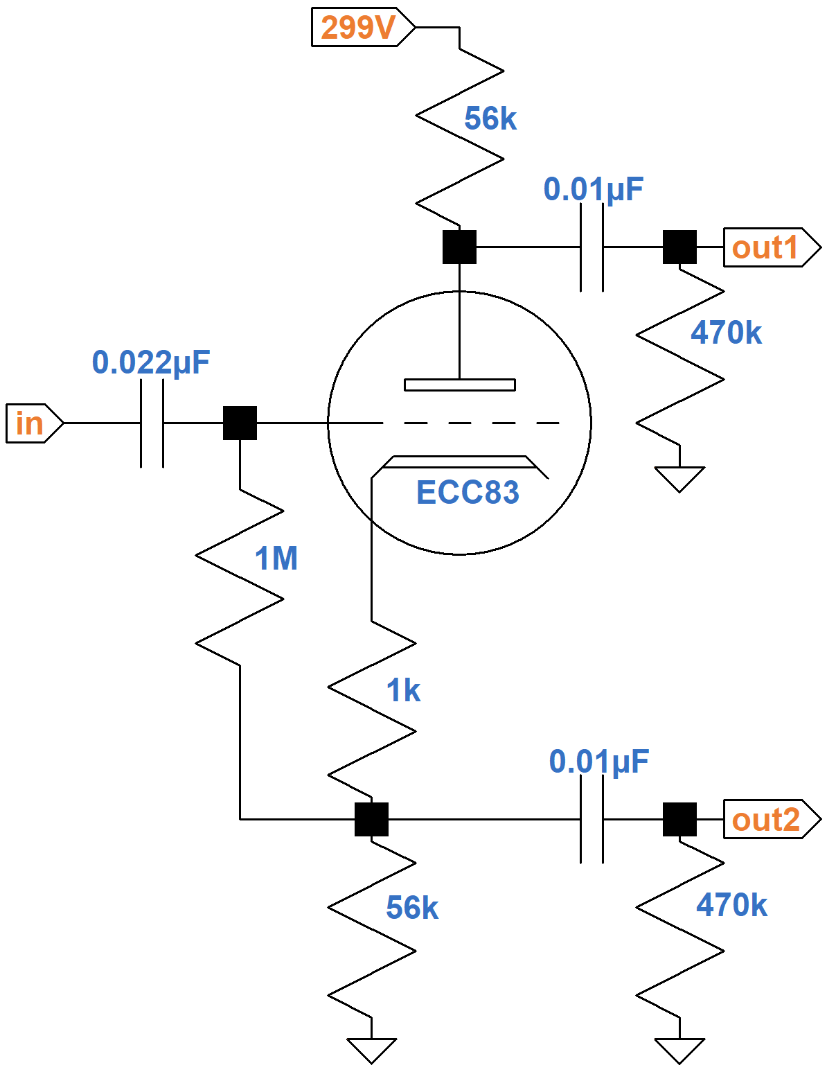
The split-load phase inverter has approximately unity gain,2 so this also represents the gain from the phase inverter input to the feedback tap.
The upstream voltage amplifier's cathode is used as the insertion point for negative feedback.
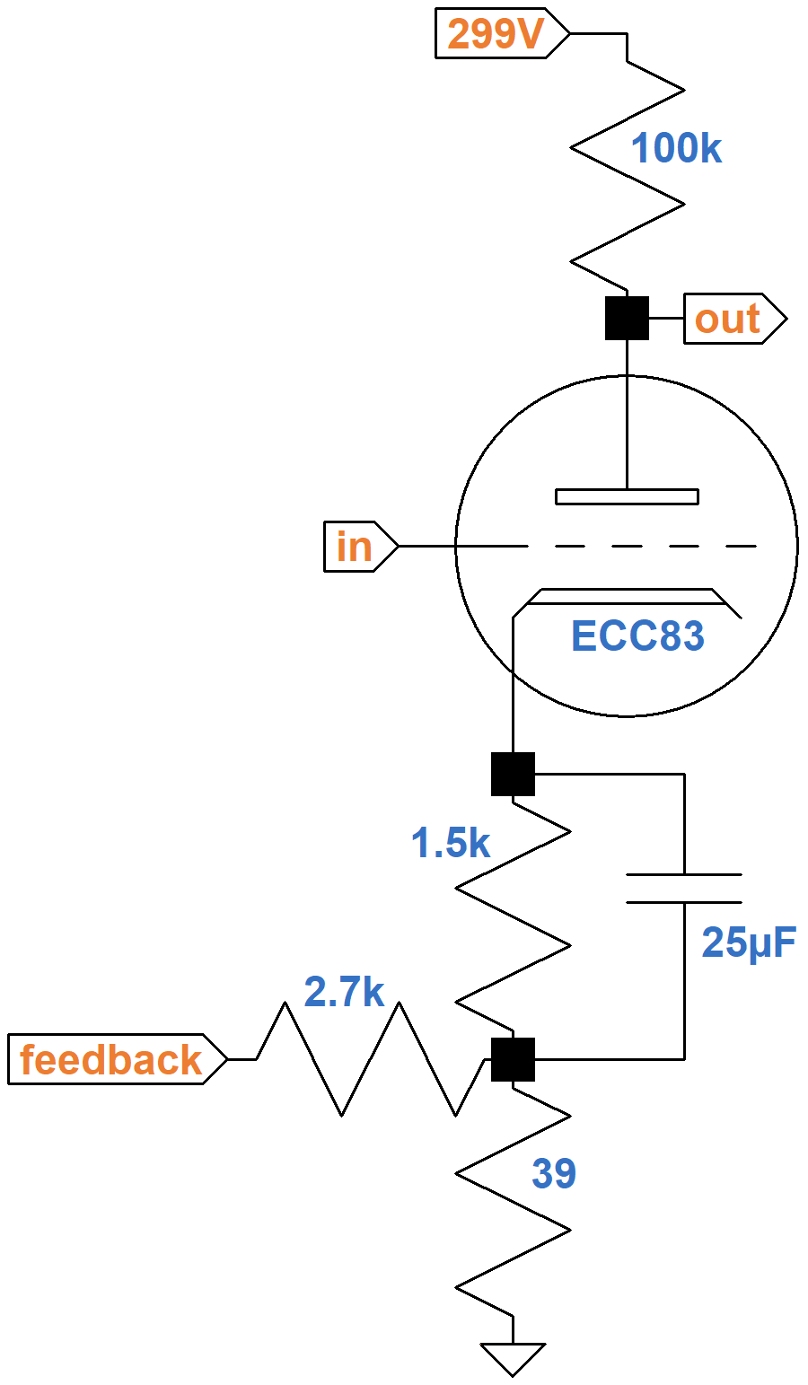
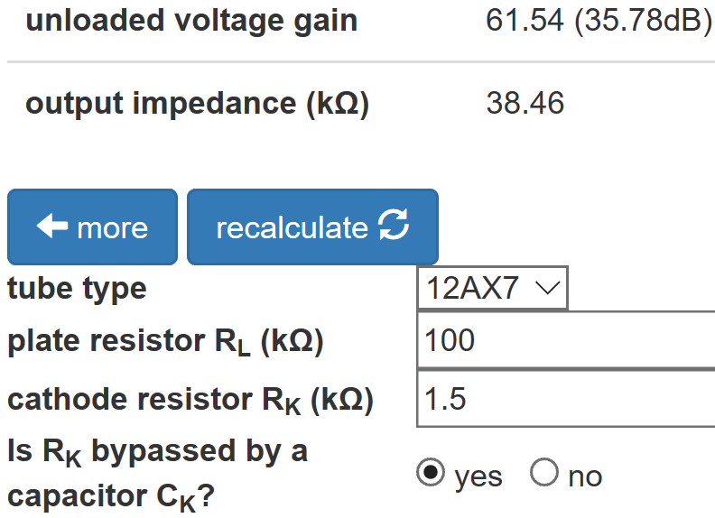
For audio signals, the 1.5kΩ cathode resistor is fully bypassed. For a signal at the grid, the 39Ω resistor is very small, so the cathode is effectively at AC ground potential. The input impedance of the phase inverter is much greater than 1MΩ, so the voltage amplifier is essentially unloaded. According to the Preamp Gain and Output Impedance calculator, the voltage gain is G1 = 61.5.
|
Fundamentals of Guitar Amplifier System Design - design your amp using a structured, professional methodology. |
The forward (open-loop) voltage gain from the voltage amplifier grid to the 8Ω transformer tap is
G = G1(G2H1) = (61.5)(1.54) = 94.7
The shunt resistance for feedback is equal to the 39Ω resistor in parallel with the cathode impedance, which can be ignored because it is more than an order of magnitude greater. The feedback gain from the output transformer secondary to the cathode is therefore based on a simple voltage divider:
H2 = 39Ω / (39Ω + 2.7kΩ) = 0.0142
When a signal drives the cathode directly, it suffers no cathode degeneration.3,4 Voltage gain is therefore the same as for a signal at the grid when the cathode resistor is fully bypassed: G3 = 61.5. The feedback voltage gain is therefore
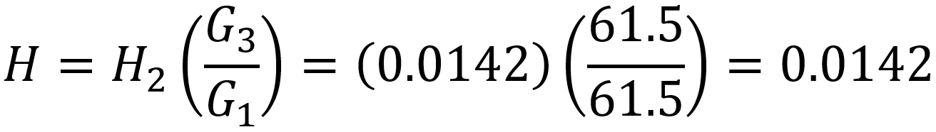
This means that when negative feedback is added, the voltage gain for the three stages decreases by
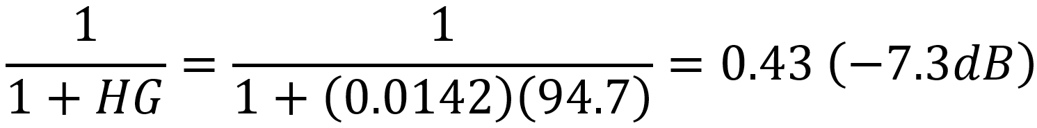
For closed-loop gain to be less than open-loop gain by only 7.3dB is modest compared to high-fidelity amplifiers, but more than many guitar amps. Negative feedback lowers the power amp's output impedance, making it more capable of handling the frequency-dependent nature of speaker impedance, particularly for bass.5
References
1Michael Doyle, The History of Marshall, (Milwaukee: Hal Leonard, 1993), p. 76.
2Richard Kuehnel, Guitar Amplifier Electronics: Basic Theory, (Seattle: Amp Books, 2018), p. 133.
3Richard Kuehnel, Guitar Amplifier Electronics: Basic Theory, (Seattle: Amp Books, 2018), pp. 61-65.
4Richard Kuehnel, Fundamentals of Guitar Amplifier System Design, (Seattle: Amp Books, 2019), p. 78.
5Richard Kuehnel, Guitar Amplifier Electronics: Basic Theory, (Seattle: Amp Books, 2018), p. 152.