Fender Parallel 12AT7 Reverb Driver
The Fender Twin Reverb AB763
Dave Hunter provides this background on Fender's parallel 12AT7 reverb circuit in the context of a 1963 Fender Twin Reverb.1
"The reverb circuit in Fender amps is very different from that in the company's three-knob outboard Reverb Unit of the early 1960s. The latter has more depth and 'sproing' and is undoubtedly the sound of surf - and maybe rockabilly-preferred tone as well - but many players prefer the smooth, round sound of the amp-based effect as typified on these blackface models. The amp-based version is just as much a real tube-driven spring reverb circuit in that it carries a small OT to drive a portion of the signal through a long-spring pan, but instead of the Reverb Unit's large 6K6 output tube, 12AT7, and 7025 (a 12AX7 type) it uses just the latter pair, one as driver and one as recovery tube. If anything, this effect is a little smoother and less dramatic than the outboard version, though it has just a single knob for depth rather than the predecessor's Mixer, Dwell, and Tone controls. In any case, it's a great sounding version of the effect for country, rock, and jazz, and together with the onboard Vibrato helped to make these deluxe mid-1960s Fenders impressive and full-featured sound machines."
The Reverb Tank
According to its data sheet, an Accutronics 4AB3C1B long-decay, 2-spring reverb tank, which is a suitable replacement for a 1963 Twin Reverb AB763, has these specifications:
- input impedance: 8Ω at 1kHz,
- output impedance: 2.25kΩ at 1kHz,
- typical decay time: 2.75 to 4.0 seconds,
- DC resistance: 0.81Ω, and
- nominal drive current: 28.0mA RMS (39.6mA peak).
To create a reactance of 8Ω at 1kHz, the inductance across the input of the tank is 8Ω / [2π(1kHz)] = 1.27mH.

|
Guitar Amplifier Electronics: Fender Deluxe - from TV front to narrow panel to brownface to blackface Reverb |
A Large-Signal SPICE Model2
To simulate the parallel 12AT7 reverb driver, let's use Andre Adrian's 12AT7 Large-Signal SPICE Model:
.SUBCKT ECC81 A G K

* 12AT7, Philips datasheet

.param mu=60 m=1.5 G=-5.79 Ga=240m Ve=154m Dg=608m

+ B=0.1 n=0.5 Vw=-61.4m Vo=86.2m Io=173u

.func f(Vg,Va) {exp(G+Ga*Vg)*(Va/mu+Dg*Vg+Ve)**m/(Va**n+B*Vg**n)}

Ra    A    A1   500

Cg    G    K    2.3p

Ca    A1   K    0.45p

Cag   A1   G    1.6p

Ba    A1   K    I=f(V(G,K),V(A1,K))*V(A1,K)**n

Bg    G    K    I=if(V(G,K)<Vw,Io*exp(V(G,K)/Vo),f(V(G,K),V(A1,K))*B*V(G,K)**n)

.ENDS
A Hammond type 1750A replacement for Fender's type 125A20B driver transformer has a primary impedance of 22.8kΩ and a secondary impedance of 8Ω. The inductance ratio of the transformer is equal to the impedance ratio: 22.8kΩ / 8Ω = 2850. (The calculated turns ratio is the square root of this value: 53.4, which is close to Hammond's data sheet value of 53.11.) For an arbitrarily chosen secondary inductance of 20mH, the primary inductance needs to be (2850)(20mH) = 57H.
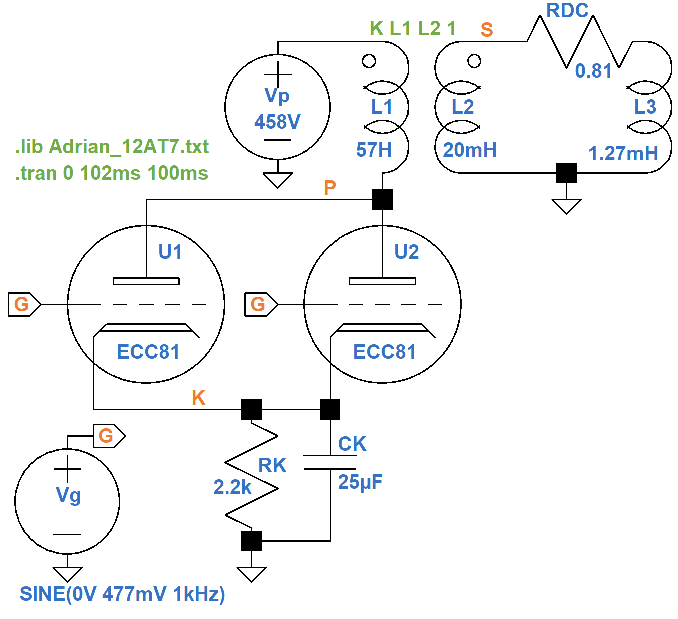
The transient simulation3 applies an input signal amplitude of 477mV peak to the 12AT7 grids, which is sufficient to create the tank's nominal drive current level at a frequency of 1kHz. Let's plot the secondary voltage and tank current over two cycles.
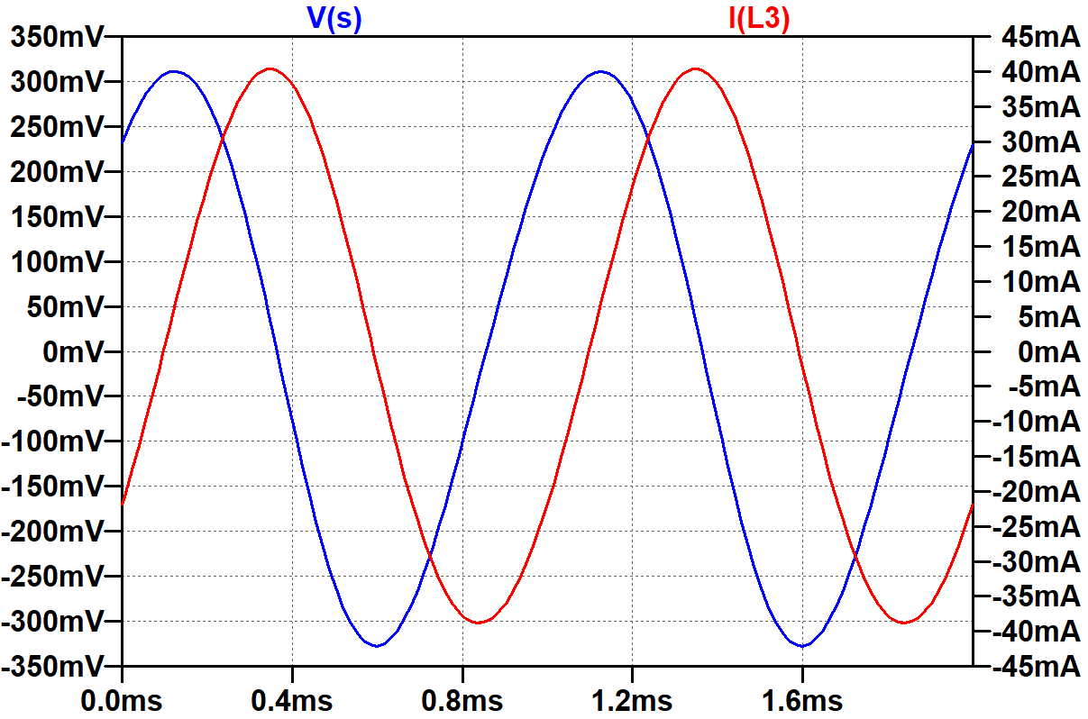
Current lags voltage by almost 90 degrees, which is expected of a highly inductive load. The simulation indicates that the RMS voltage is 225mV. RMS current measures 28mA, for an effective impedance of 225mV / 28mA = 8Ω.
|
Guitar Amplifier Electronics: Basic Theory - master the basics of preamp, power amp, and power supply design. |
If we run a DC operating point simulation,4 we see that each triode operates at a grid-to-cathode voltage of -8.2VDC. (Fender measures -8.6VDC for the Twin Reverb AB763.) The plate-to-cathode voltage is 449.8VDC. (Fender measures 431.4VDC. This accounts for DC winding resistance in the transformer primary, which we do not include in our SPICE simulation.) The DC plate current is 1.86mA per tube. Here is a plot of AC plate-to-cathode voltage and AC plate current for one tube.
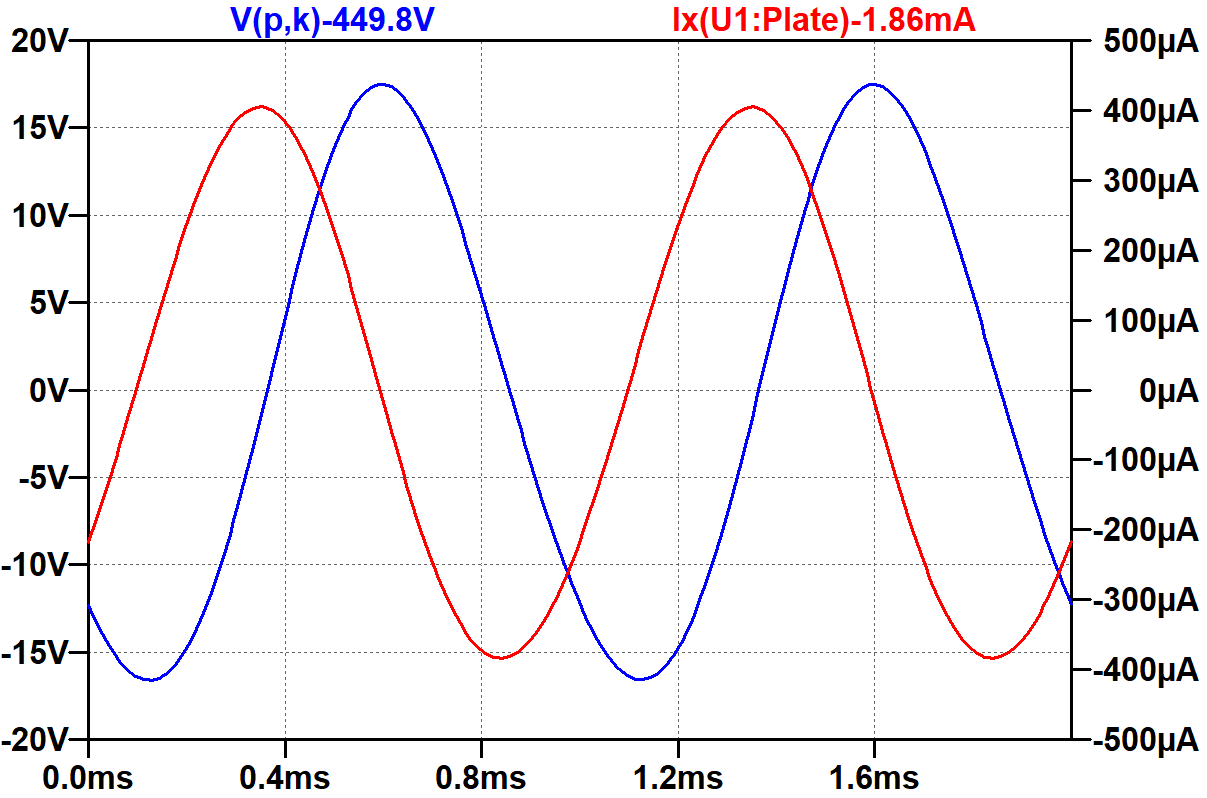
RMS voltage is 12V and RMS current is 279μA, for an effective calculated impedance of 12V / 279μA = 43kΩ per tube, i.e. 21.5kΩ for the two tubes in parallel. This is close to the 22.8kΩ impedance of the transformer primary.
|
Fundamentals of Guitar Amplifier System Design - design your amp using a structured, professional methodology. |
Input Sensitivity
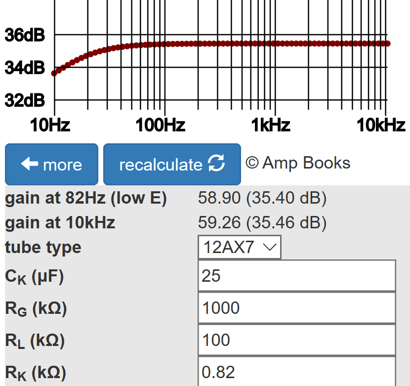
At the tube grids, 447mV peak is required to drive the tank at nominal current for a 1kHz signal. According to the Cathode Bypass Capacitor calculator, the upstream voltage amplification stage has a voltage gain of 59, so to fully drive the tank, the signal level at its grid is 447mV / 59 = 7.6mV peak.
Upstream of the second stage is a tone stack and gain control. With the control at 50-percent rotation, 10-percent resistance, its voltage "gain" is 0.1. The tone stack in front of it has a "gain" of -25.6dB (a voltage gain of 0.052) with all controls at noon.5 The first stage has a voltage gain of 59, so the signal level at the guitar input jack is 7.6mV / 0.1 / 0.052 / 59 = 25mV peak (-35dBV). This represents the input sensitivity for a fully driven reverb tank with all controls at 50-percent rotation, which is easily achieved by single-coil pickups.
|
Guitar Amplifier Electronics: Circuit Simulation - know your design works by measuring performance at every point in the amplifier. |
Voicing6
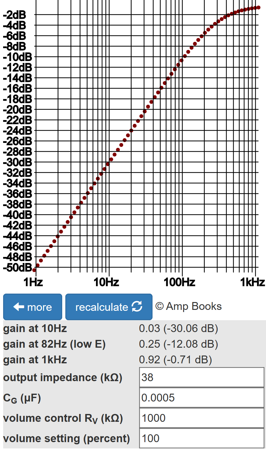
The input impedance to the reverb tank is almost purely reactive and proportional to signal frequency. Bass drives more current and can unpleasantly dominate the reverberated response. To mitigate this effect, Fender attenuates bass through the use of a tiny, 500pF coupling capacitor between the second-stage voltage amplifier and the 12AT7 grids. According to the Coupling Capacitor calculator, there is -12dB gain at 82Hz, the lowest note on a guitar with standard tuning.
The Results?
All in all, Fender's design is a great compliment to the classic Fender Twin Reverb.
"Package it with a tube-driven, long-pan spring reverb also built into this combo ... and you've got an impressive performance package that's primed to take on virtually any stage - or was in the mid-1960s." -Dave Hunter7
References
1Dave Hunter, Guitar Rigs: Classic Guitar & Amp Combinations, (San Francisco: Backbeat Books, 2005), p. 157.
2Richard Kuehnel, Guitar Amplifier Electronics: Circuit Simulation, (Seattle: Amp Books, 2019), pp. 86-99.
3Richard Kuehnel, Guitar Amplifier Electronics: Circuit Simulation, (Seattle: Amp Books, 2019), p. 46.
4Richard Kuehnel, Guitar Amplifier Electronics: Circuit Simulation, (Seattle: Amp Books, 2019), pp. 32, 136, 184.
5Richard Kuehnel, Guitar Amplifier Electronics: Basic Theory, (Seattle: Amp Books, 2018), p.94.
6Richard Kuehnel, Guitar Amplifier Electronics: System Design, (Seattle: Amp Books, 2019), pp. 114-134.
7Dave Hunter, Amped, (Minneapolis: Voyageur Press, 2012), p. 111.
