Circuit Analysis of the Watkins Dominator
With its classic V-front, Charlie Watkins' 1963 Dominator gets rave reviews for its unique cabinetry, which can overshadow its superbly designed tremolo and its uncluttered signal path to EL84 goodness.
"The mids and highs are sparkly clean, with warmth and depth. Push the volume and you still have control, with a clear, round tone; and if you play with attack, the amp responds with a gratifying growl. It also has a fantastic tremolo that washes over you as you play." 1 -Marcel Cavallé
The amp has two channels: a "normal" microphone channel and a "tremolo channel" for guitar. The latter begins with an ECC83/12AX7 voltage amplifier with footswitchable tremolo and ends with an EL84 push-pull power amp with cathode bias and no negative feedback.
First Stage Preamp
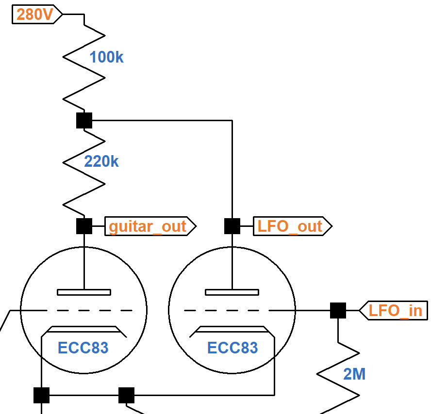
The first stage contains a voltage amplifier (left triode) and low-frequency oscillator (right triode).
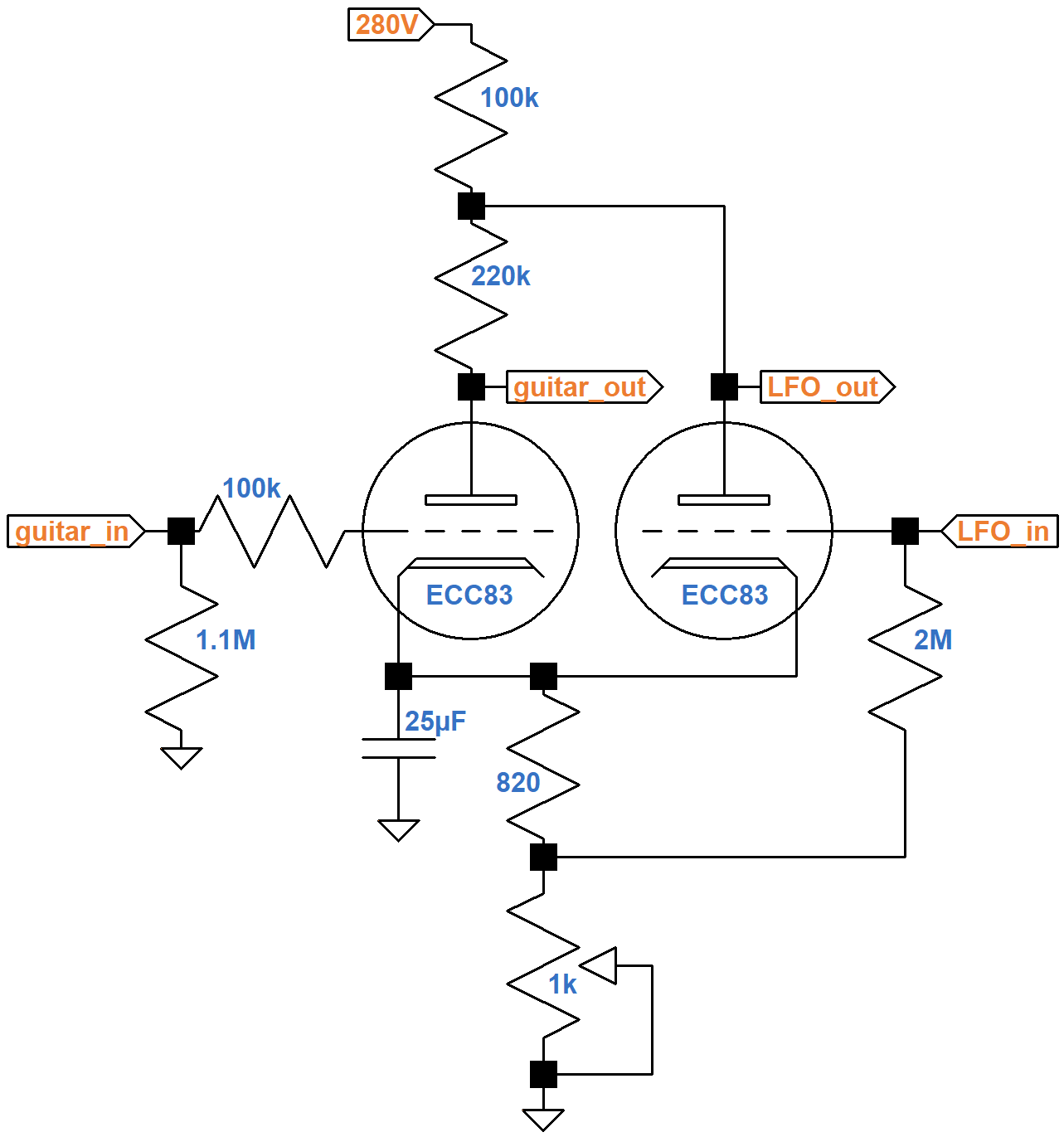
If the top of the 220kΩ resistor were connected directly to the 280V plate supply and if the bottom of the 820Ω resistor were connected directly to ground, then the left triode would create a traditional voltage amplifier with constant gain. The right triode and the circuitry connected to its input and output create a low-frequency oscillator (LFO) to create a signal of a few hertz. The LFO signal controls the gain of the voltage amplifier, a process known as amplitude modulation. To see how this works, let's look at the similar, but simpler tremolo circuit found in the Gibson Skylark.
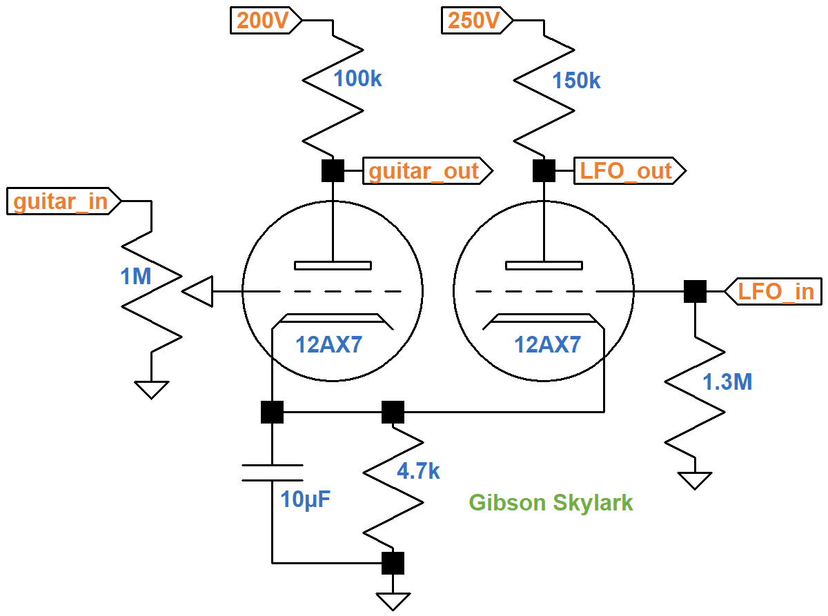
The reactance of the 10μF cathode bypass capacitor is 194Ω at 82Hz, the lowest note on a guitar, effectively shorting the 4.7kΩ cathode resistor. This holds the cathode voltage steady for maximum gain - the cathode voltage does not react to audio an audio signal. For a 5Hz tremolo signal, the capacitor's reactance increases to 3.2kΩ, which is insufficient to hold the cathode voltage steady. The LFO slowly varies the cathode voltage, which changes the DC operating point for the voltage amplifier, thereby affecting its gain.
|
Guitar Amplifier Electronics: Fender Deluxe - from TV front to narrow panel to brownface to blackface Reverb |
There are side effects. If the LFO input voltage increases, plate current in the right triode increases, which increases the total current flowing through the 4.7kΩ resistor. This increases the cathode voltage, causing the grid-to-cathode voltage for the left triode to decrease, causing less plate current to flow through the 100kΩ resistor, reducing the voltage across it, which increases the voltage at the guitar signal output. The LFO signal gets amplified by the circuit and passes to the next stage, potentially even overdriving it at a sub-audio frequency. For the Watkins Dominator, it is important to note that the LFO signal at the guitar signal output is in phase with the LFO input signal.
To help prevent this unwanted side effect, the Dominator's triodes share a 100kΩ plate load.
When the LFO input voltage increases, plate current in the right triode increases, which draws more current through the 100kΩ resistor, causing the voltage across it to increase and the plate voltage of the left triode to decrease. Since this effect is of opposite phase, it helps counteract the side effect of the Skylark circuit.
|
Guitar Amplifier Electronics: Basic Theory - master the basics of preamp, power amp, and power supply design. |
1st Stage DC Conditions
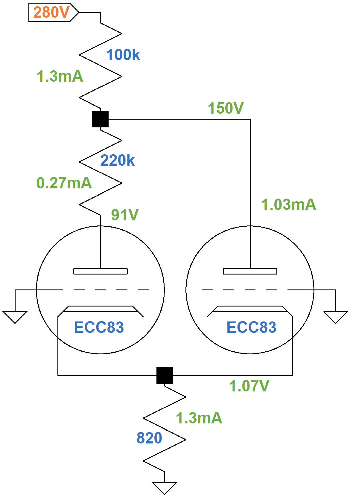
Under DC conditions, there is no guitar signal and no LFO signal. Capacitors are open circuits. No grid current flows, so there is no voltage drop across the resistors that connect the grids to ground. Thus both grids are at ground potential. Here is the DC equivalent circuit with the depth control set to zero resistance.
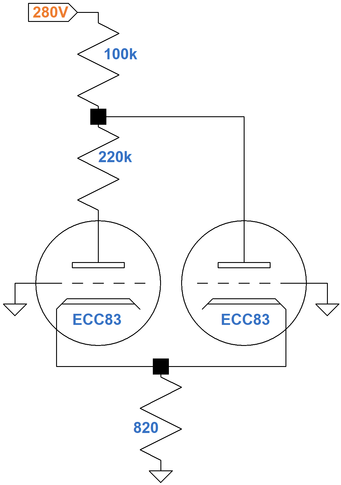
The circuit looks unusual because the second triode shares only part of the 320kΩ total plate load. Separate plate load resistors could be handled like a long-tailed-pair phase inverter.2 A fully shared resistor could be handled like the Gretsch Chet Atkins active mixer. We need an ad hoc solution to find the DC operating points.
The plate current of two tubes passes through the 820Ω cathode resistor. According to Ohm's Law, If the cathode voltage is 2V (a grid-to-cathode voltage of -2V), the current through the resistor is
2V / 820Ω = 2.44mA
This is one endpoint of the red line on the transfer characteristics that depicts the relationship between DC grid bias and the total plate current of the two triodes.
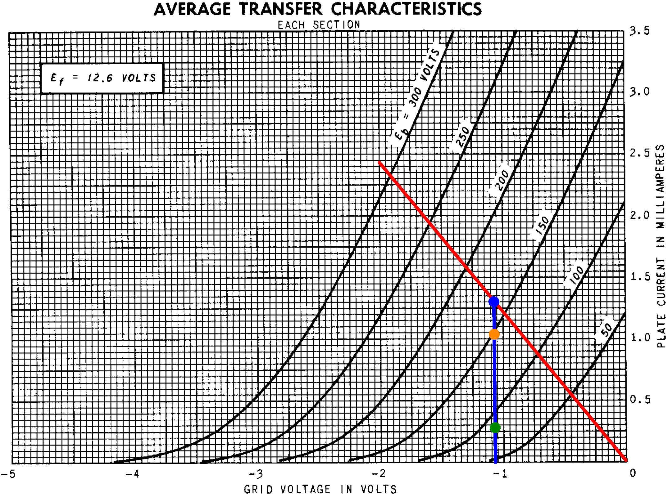
The DC grid bias is the same for both triodes, so their DC operating points will be on the same vertical line, such as the blue line shown for a grid voltage of -1.07V. (After a few bad guesses for the bias voltage, which will not be repeated here, a value of -1.07V appears to work.) According to Ohms' Law, the current through the cathode resistor is
1.07V / 820Ω = 1.3mA
This is the total plate current for two triodes (blue dot). This current also passes through the 100kΩ resistor, so the voltage drop across it is
(1.3mA)(100kΩ) = 130V
The plate-to-ground voltage for the right triode is therefore
280V - 130V = 150V
The cathode-to-ground voltage is 1.07V, so the right triode has a plate-to-cathode voltage of 149V (orange dot). According to the transfer characteristics, the plate current is 1.03mA.
The plate current for the left triode must be equal to the total current passing through the cathode resistor minus the plate current for the right triode:
1.3mA - 1.03mA = 0.27mA (green dot)
The voltage drop across the 220kΩ resistor is
(0.27mA)(220kΩ) = 59V
The plate-to-ground voltage for the left triode is therefore
150V - 59V = 91V
According to the transfer characteristics, for a plate current of 0.27mA (green dot) the plate-to-cathode voltage appears to be about 90V. Here are the calculated DC conditions for an average tube based on 12AX7 transfer characteristics.
|
Fundamentals of Guitar Amplifier System Design - design your amp using a structured, professional methodology. |
AC Small-Signal Parameters
At only 0.27mA, plate current is unusually low for the voltage amplifier. The first stage of the Fender Champ 5E1, for example, draws almost 1mA plate current. According to 12AX7 characteristics, the amplification factor μ is 98, the plate resistance rp is 114kΩ, and the transconductance gm is 0.86mS.
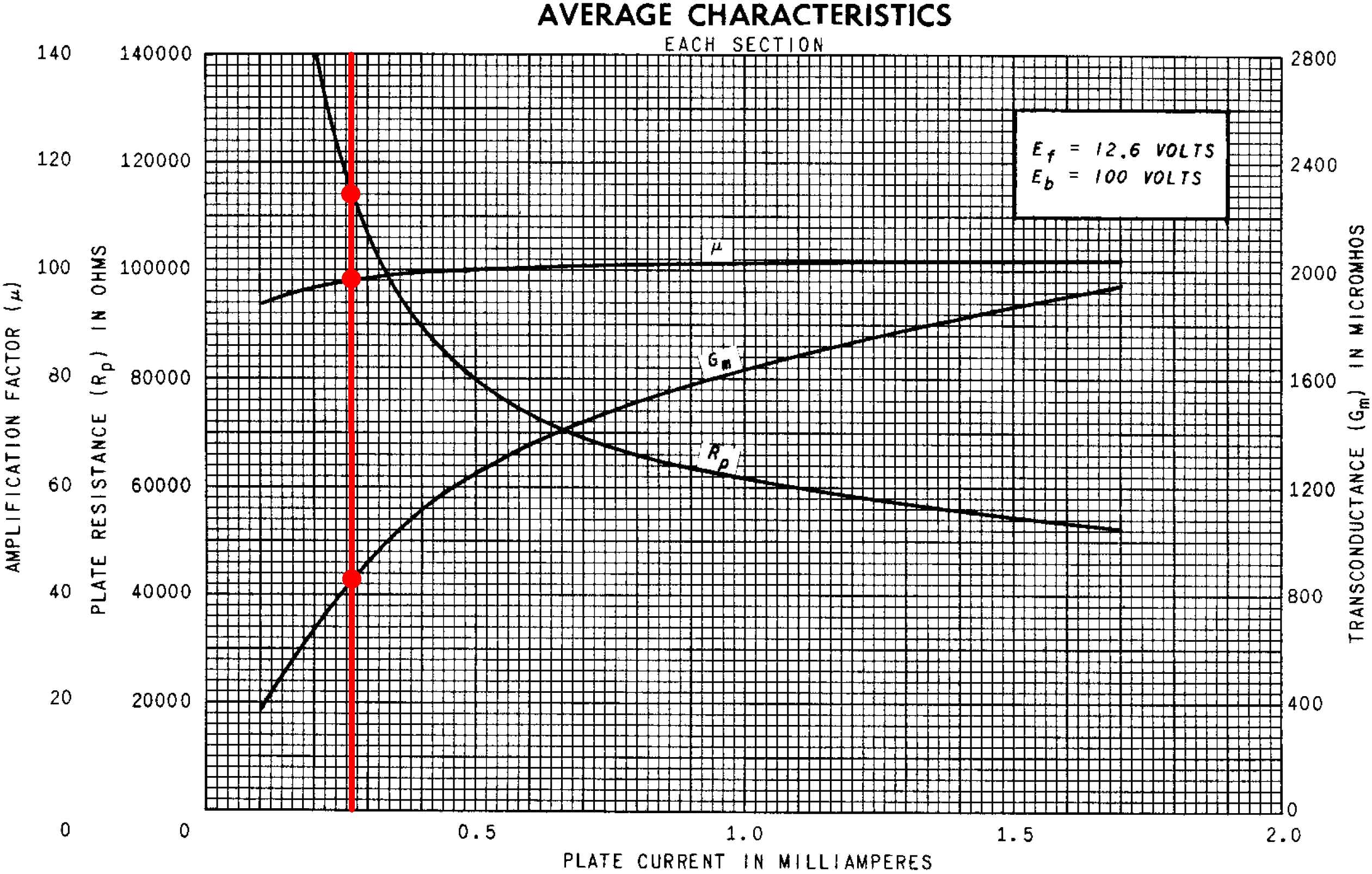
High plate resistance and low transconductance create less loaded gain. The key to the design, however, is not the amount of gain per se - it is the ability for the gain to change when the operating point shifts. The triode is biased at points where the slope of the plate resistance and transconductance curves are steep. This maximizes the effect of a shift in operating point, giving the tremolo oscillator greater control over voltage amplifier gain.
The Low-Frequency Oscillator (LFO)
The LFO has a footswitch interface and a speed control.
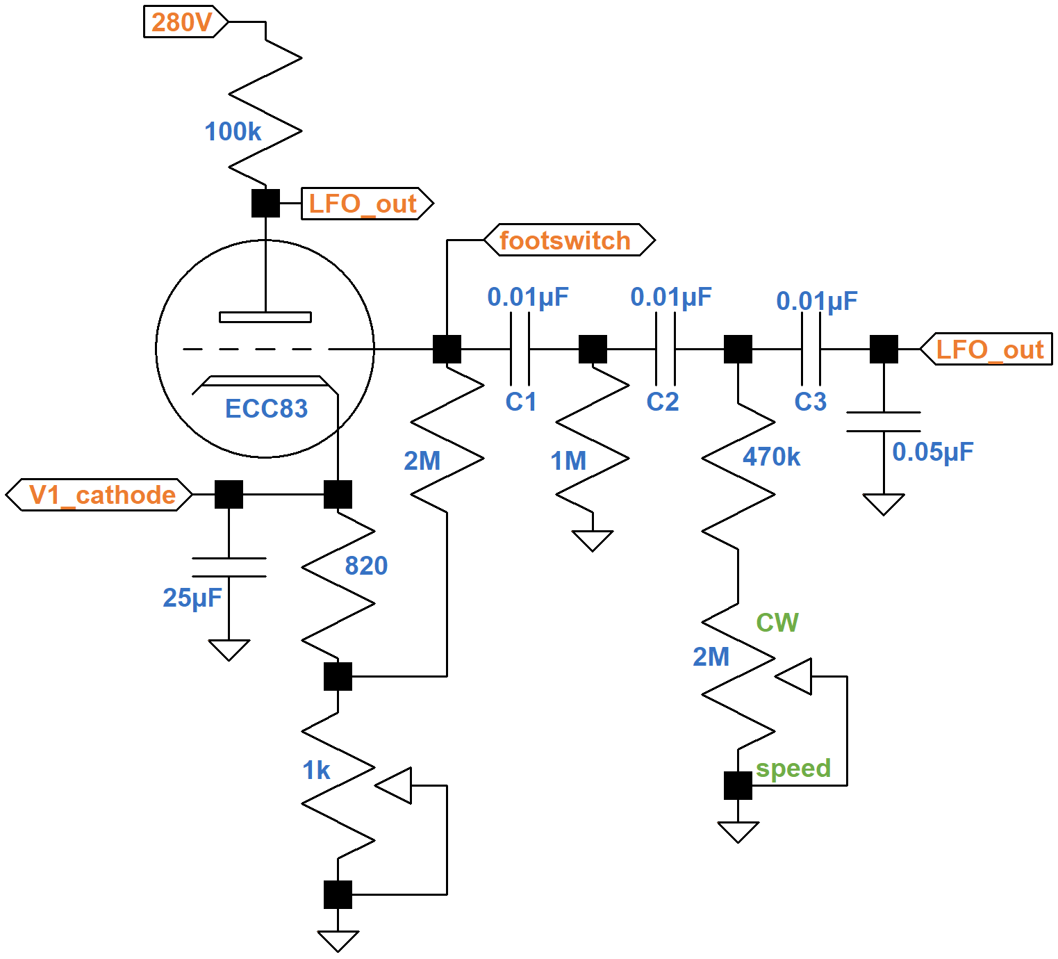
As the signal passes through each of the three capacitors C1, C2, and C3, the phase of the LFO signal changes. At the resonant frequency, which is controlled by the speed control, the signal at the grid is in phase with the signal at the plate, resulting in positive feedback that sustains the oscillation. For a more detailed explanation of this type of circuit, see The Fender Vibroverb 6G16 Tremolo Circuit.
|
Guitar Amplifier Electronics: Circuit Simulation - know your design works by measuring performance at every point in the amplifier. |
High-Pass Filter and Tone Control
To attenuate the raw LFO signal that is mixed with the modulated guitar signal, the Dominator includes a high-pass filter upstream of the tone control and volume control.
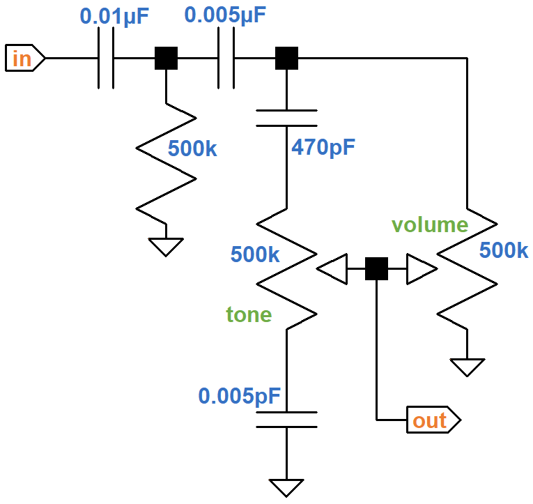
Using a SPICE AC analysis simulation,4 here is the response with the volume control at 50-percent rotation (10-percent resistance) and the tone control at minimum, 50-percent resistance, 90-percent resistance, and maximum.
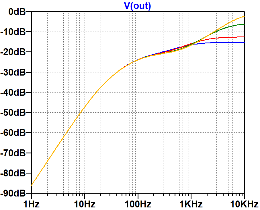
There is severe attenuation for tremolo frequencies. Even with the volume control at maximum, there is 38dB attenuation at 10Hz. The tone control adds variable treble cut, affecting only frequencies above 1kHz.
The Long-Tailed-Pair Phase Inverter
The phase inverter unites the "normal" microphone channel with the "tremolo" guitar channel. The unused channel serves as LTP's grounded input.
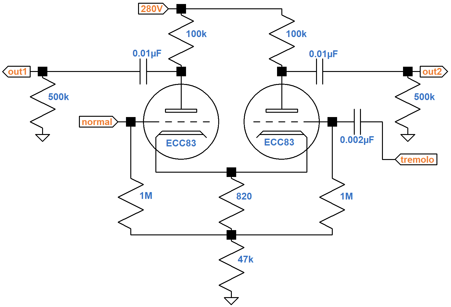
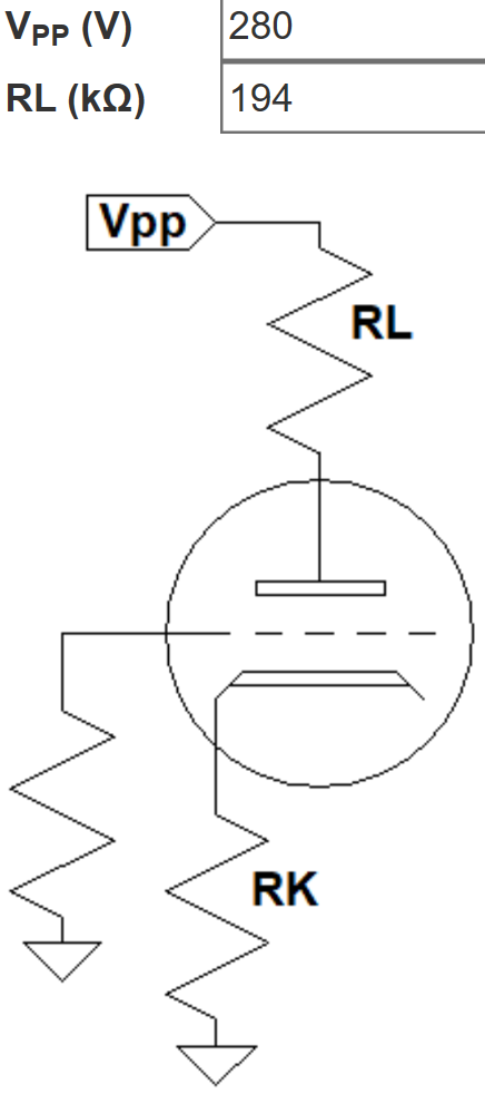
The resistors connecting the cathodes to ground carry the current of two triodes, so for the purposes of determining the DC operating point, the equivalent circuit for one triode doubles the resistor values. This puts a total of 100kΩ + 94kΩ = 194kΩ plus the bias resistor in series with the tube. According to the 12AX7 calculator, the effective 1.64kΩ bias resistor creates a DC grid bias of -1.2V.
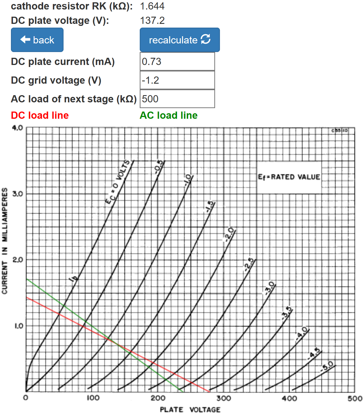
The total DC plate supply current for two triodes is double the amount shown: about 1.5mA.
According to the Long Tailed Pair calculator, the 47kΩ resistor creates a large "tail" to balance the inverted and non-inverted gains.
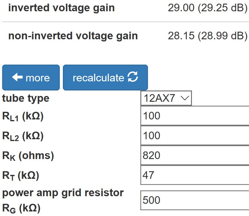
When the tail is large enough, reducing the value of the plate load resistor for the inverted output, as in the Fender Bassman 5F6-A, is unnecessary.
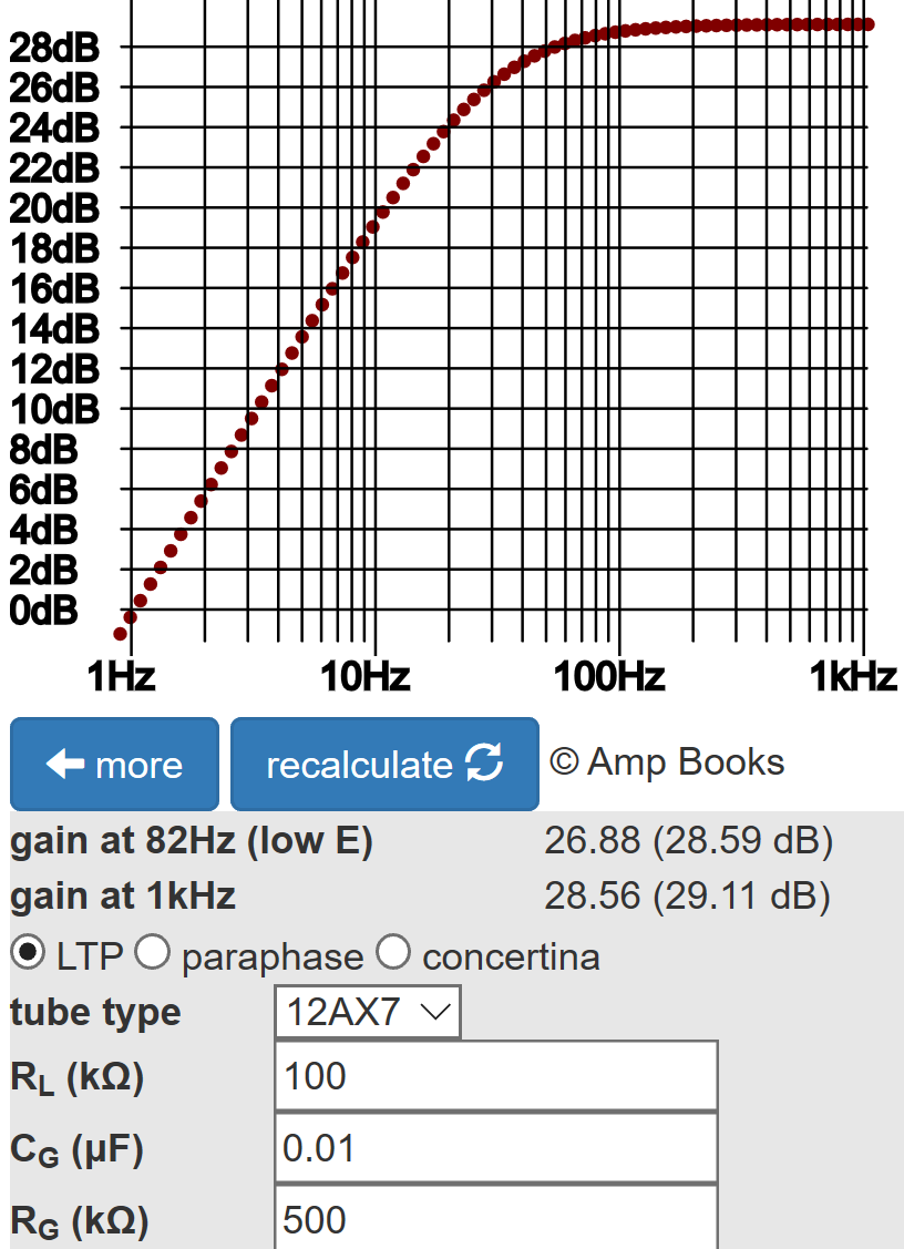
The Phase Inverter Bass Response calculator shows that the 0.01μF coupling capacitors create only half a decibel of attenuation at 82Hz, the lowest note of a guitar with standard tuning.
The Power Amp
The power amp has two EL84 pentodes in push-pull with cathode bias.
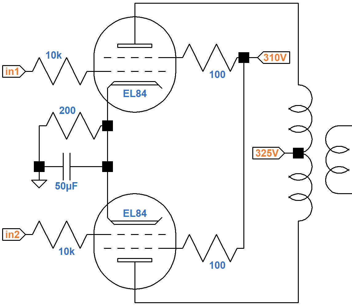
A Sovtek EL84 data sheet includes plate and screen transfer characteristics when both the plate and screen are at 300V. Using the upper solid curve for plate current and the upper dashed curve for screen current, we see that for a -6.6V grid, the plate current is 65mA and the screen current is 5mA, as depicted by where the red line crosses the two curves.
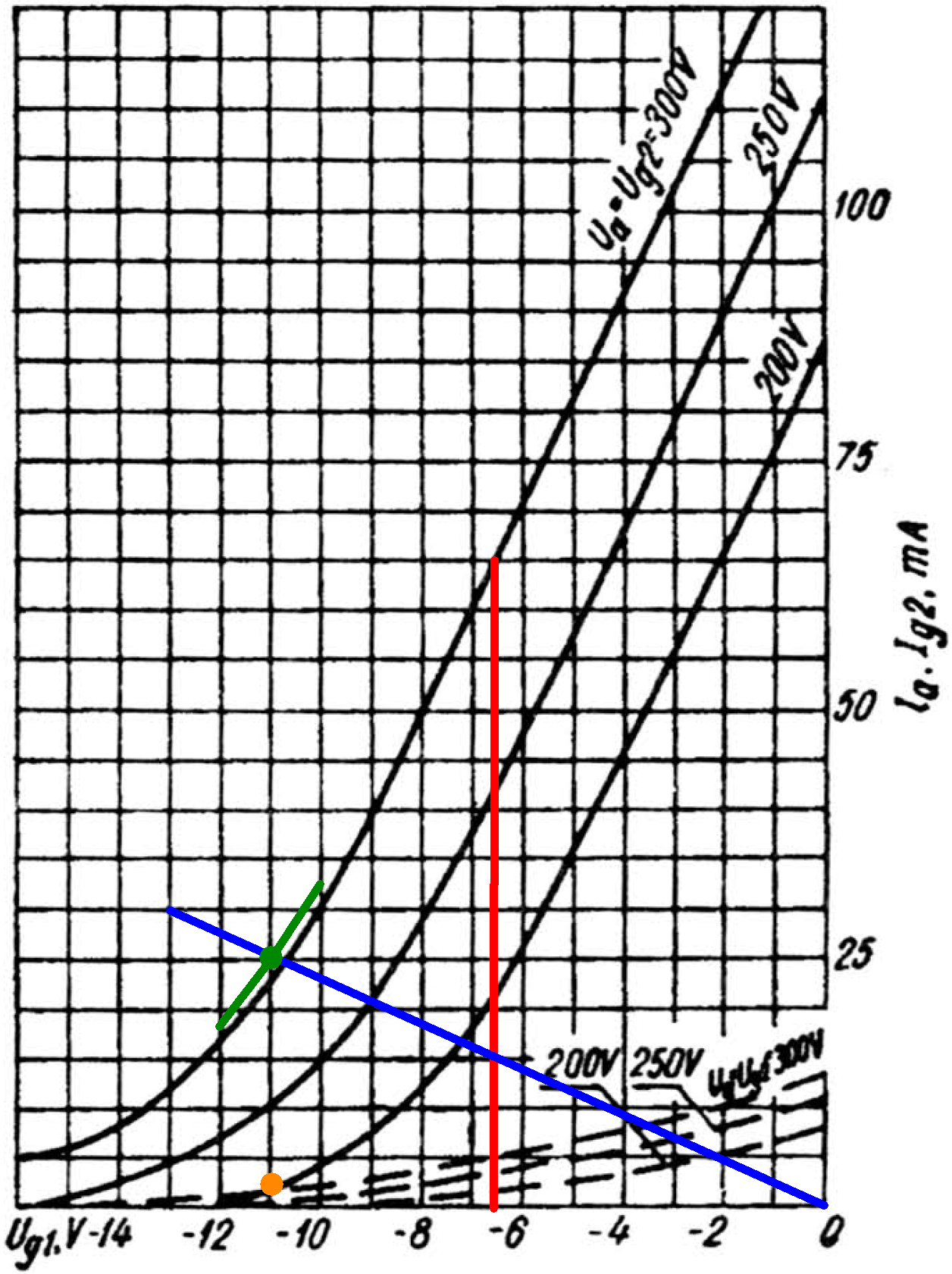
The cathode current is their sum: 70mA. Assuming the ratio of plate current to screen current is approximately constant, the ratio of cathode current to plate current is also constant:
(70mA) / (65mA) = 1.07
The cathode resistor carries the plate and screen current for two tubes, so its equivalent value for one tube is double: 400Ω. If the plate current is 30mA, then according to Ohm's Law the voltage across the cathode resistor is
(1.07)(30mA)(400Ω) = 13V
A grid voltage of -13V and a plate current of 30mA is one endpoint of the blue line. If there is no plate current the voltage across the cathode resistor is 0V, so the other endpoint represents a 0V grid and 0mA plate current.
If the DC grid bias is -10V, then the cathode is at 10V and the screen-to-cathode voltage is 315V - 10V = 305V. If the grid bias is -11V or -12V, then the screen voltage is 304V or 303V, respectively. These are the endpoints of the green line segments.
The intersection of the blue and green lines is slightly above the plate current curve for a 300V screen (green dot), indicating the DC plate current is 25mA for one tube. A corresponding orange dot is placed slightly above the dashed screen current curve, which indicates the screen current is 2mA.
Based on this analysis, this is our estimate of the DC operating point for an average set of tubes:
- a grid bias in the neighborhood of -11V,
- a screen-to-cathode voltage of 304V, and
- a cathode current (screen current plus plate current) of 27mA per tube.
The screen voltage is barely above 300V, so we can use 300V plate characteristics.
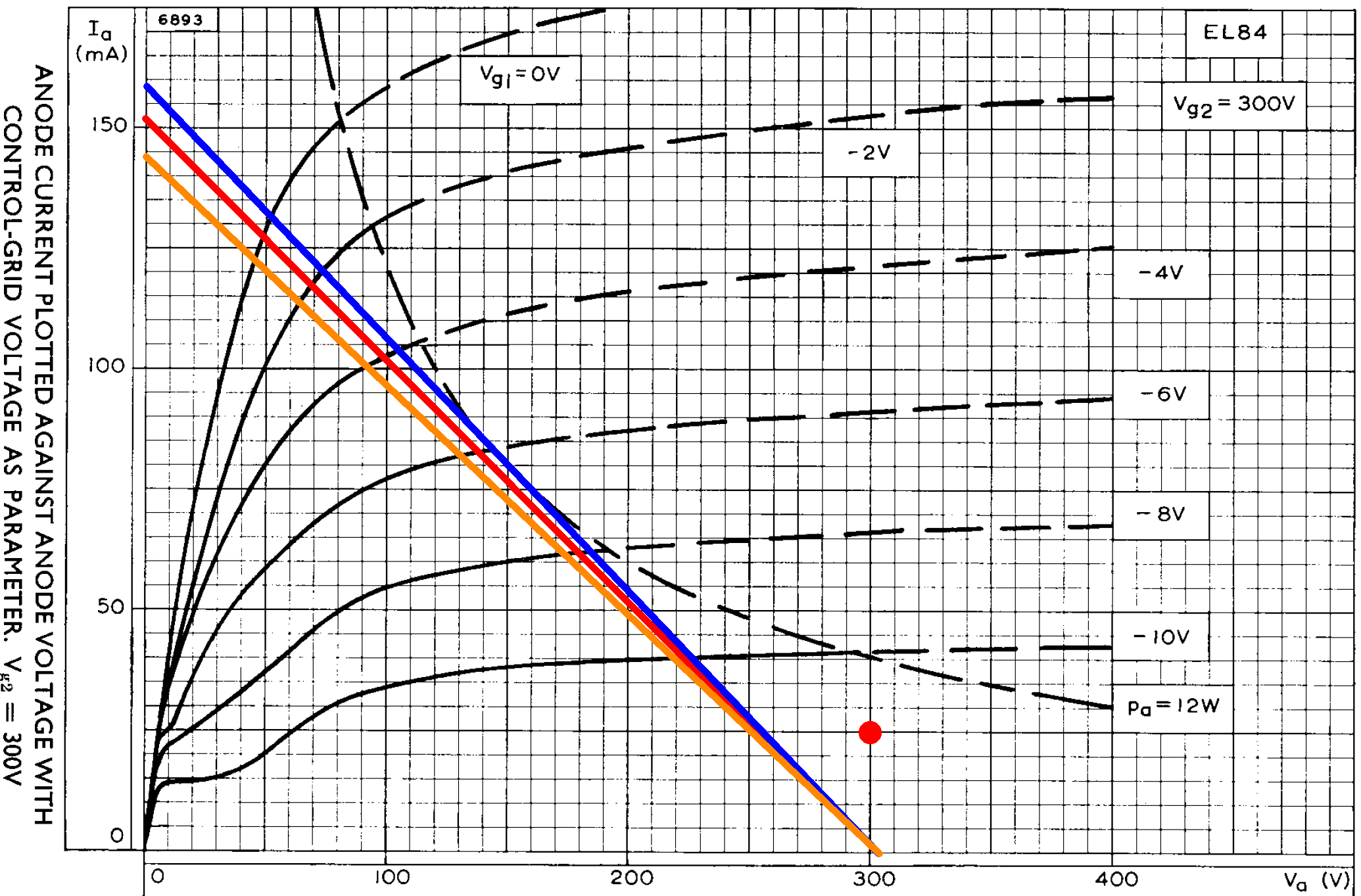
Let's assume an 8kΩ plate-to-plate primary impedance for the output transformer, like the Vox AC15. If we approximate audio performance by assuming pure Class B operation, we divide the 8kΩ plate-to-plate primary impedance by 4 and plot a 2kΩ load line (red). If the plate voltage swings from 304V down to 0V, the plate current increases from 0mA to
304V / 2kΩ = 152mA
The red load line therefore connects 304V, 0mA and 0V, 152mA. The red dot is the DC operating point.
The load line crosses the 0V grid curve at a plate voltage of 49V and a plate current of 127mA, so output power is in the neighborhood of
(304V - 49V)(127mA) / 2 = 16W
The orange line is for a plate-to-plate primary impedance of 7.86kΩ, which may have been used for the original Dominator. The blue line is for 8.4kΩ, which is often used for clones of Marshall's 18-watt amp, which is almost identical to the Dominator circuit. The differences in primary impedance are not of much consequence, particularly when driving a reactive load.
References
1Dave Hunter, "The Watkins Dominator Crying V," Vintage Guitar, March 2017.
2Richard Kuehnel, Guitar Amplifier Electronics: Basic Theory, (Seattle: Amp Books, 2018), pp. 134-141.
3Richard Kuehnel, Guitar Amplifier Electronics: Circuit Simulation, (Seattle: Amp Books, 2019), pp. 87-92.
4Richard Kuehnel, Guitar Amplifier Electronics: Circuit Simulation, (Seattle: Amp Books, 2019), p. 16.