Foldover Noise in Guitar Amplifier Digital Models
Vacuum tube guitar amplifiers are susceptible to multiple sources of noise. Digital modeling of an amp, its nonlinear behavior in particular, introduces an entirely new source, one that Leo Fender and Jim Marshall never had to tackle: foldover noise. Line 6 describes the severity of the problem:
"Nonlinear functions can produce high-frequency harmonics with significant amplitude. The emulation of tube distortion is one such function. Aforementioned examples of digital implementations of tube distortion suffer from this foldover noise, and are of limited usefulness. If foldover noise is not dealt with, each high note will cause the amplifier to output nonharmonic frequencies. Foldover noise is especially noticeable if the input frequency is swept, for example, when a guitar note bends up or down in pitch. In this case, the foldover artifacts sweep in frequencies which are nonharmonically related to the pitch of the guitar note and they typically sweep in the opposite direction of the guitar note sweeping." 1
What is foldover noise?
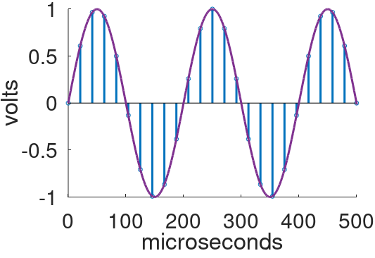
Consider the first two milliseconds of a 1kHz sine wave with a 1V amplitude.
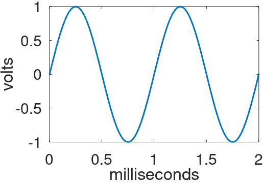
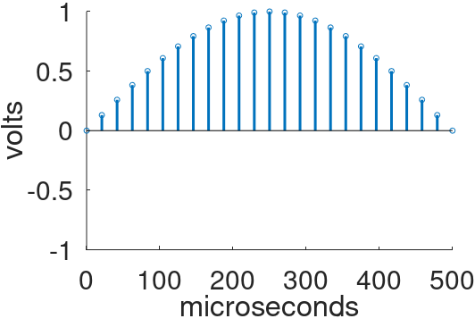
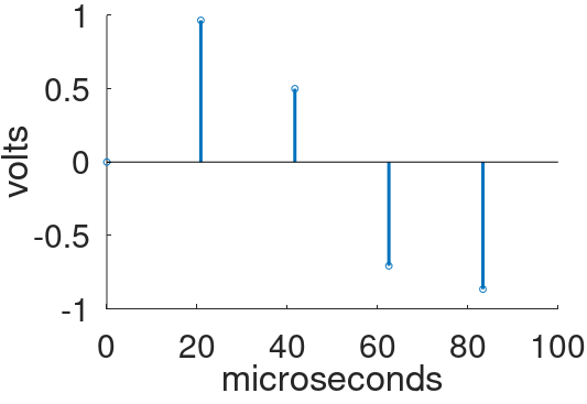
Let's digitize it by sampling at a sample rate of 48kHz. The sample period is 1 / 48kHz = 20.8 microseconds. An analog-to-digital converter (ADC), such as the one in my Focusrite Scarlett audio interface, measures the signal voltage every 20.8 microseconds and records the value as a digital sample. Let's zoom in on the samples recorded over the first 500 microseconds.
|
Guitar Amplifier Electronics: Fender Deluxe - from TV front to narrow panel to brownface to blackface Reverb |
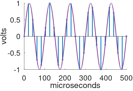
Let's increase the signal frequency to 5kHz. Here is the analog signal and the individual samples.
This time sampling is sparse - there are less than a dozen samples to completely describe the first cycle. Nevertheless, a digital-to-analog converter (DAC), such as the one in my Scarlett, can accurately recreate the original analog waveform from the digital samples. There is a mathematical limit, however. The highest frequency that can be represented by digital samples is half the sample rate. This is called the Nyquist frequency. It is also called the foldover frequency. If a guitar amp is modeled without regard to the foldover frequency, foldover noise is the likely result.
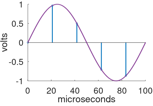
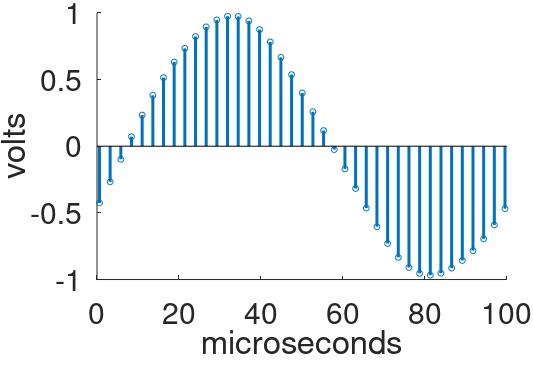
To investigate, let's increase the signal frequency to 10kHz, which is still safely below the 24kHz foldover frequency for a 48kHz sample rate.
Here we zoom in on the first cycle.
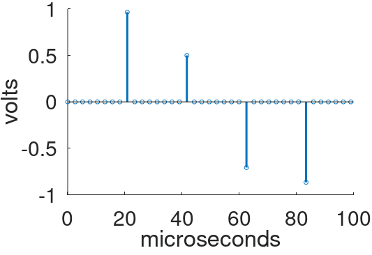
For comparison, here are samples from a signal with a frequency of 38kHz, well above the foldover frequency.
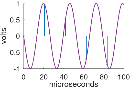
The digital samples are identical. If the sampled 38kHz signal is sent to a DAC, it converts them into 10kHz analog noise. (This phenomenon does not occur in practice. To eliminate foldover during the sampling process, an analog, low-pass, anti-aliasing filter is applied to the signal prior to sampling.) The original frequency and the noise frequency are related - they are equidistant from the 24kHz foldover frequency. The former is 14kHz higher and the latter is 14kHz lower.

|
Guitar Amplifier Electronics: Basic Theory - master the basics of preamp, power amp, and power supply design. |
Let's suppose that a guitar player bends the first string, 12th fret (E, 659.3Hz) up by half a step (F, 698.5Hz). The string creates more than a perfect sine wave limited to these frequencies. It also generates higher-frequency harmonics. The string's 10th harmonic bends from 6.593kHz to 6.985kHz. Suppose we process it through a guitar amp digital model that applies a nonlinear transfer function to create new harmonic frequencies based on the original string harmonics. The 6th harmonic of the guitar's 10th harmonic, for example, bends upward from 40kHz to 42kHz. The difference between 40kHz and the foldover frequency is
40kHz - 24kHz = 16kHz
The difference between 42kHz and the foldover frequency is
42khz - 24kHz = 18kHz
The foldover noise therefore bends downward from
24kHz - 16kHz = 8kHz
to
24kHz - 18kHz = 6kHz
It is quite disconcerting to hear harmonically unrelated foldover frequencies bending down as a string bends up. This is not a desirable artifact!
|
Fundamentals of Guitar Amplifier System Design - design your amp using a structured, professional methodology. |
How do we eliminate foldover noise?
The cure for foldover noise is described in a Line 6 patent.1
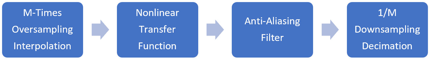
- The sample rate is temporarily increased by a factor of M, a process called upsampling or oversampling.
- Guitar amplifier distortion, which can be modeled as a nonlinear transfer function, is applied to the new sample sequence.
- A low-pass, anti-aliasing filter is applied to the resulting sequence to eliminate any frequencies that can fold over.
- The sample rate is then safely reduced to its original rate, a process known as decimation.
To see the motivation behind the technique, suppose we temporarily increase our 48kHz sample rate by a factor 8 to 384kHz. For the same 12th-fret bend, if nonlinear distortion creates a harmonic that bends from 40kHz up to 42kHz, frequencies that are now well below the new, 192kHz foldover frequency, they can be eliminated by the anti-aliasing filter prior to reducing the sample rate back to 48kHz.
There is more than one way to upsample a digital sequence. Suppose we have a 10kHz sine wave sampled at 48kHz that we want to upsample by a factor of M=8 to a new sample rate of 384kHz.
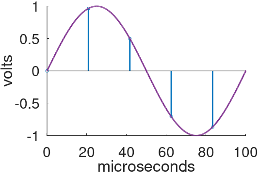
The original analog signal shown above has been converted into 5 digital samples, representing a sample rate of 48kHz. For upsampling, Line 6 prefers linear interpolation.1 For M=8, a total of 7 new samples are inserted on a line between each existing pair of samples.
Another widely used method of oversampling is to insert M-1 samples with a value of zero between each existing pair of samples. This technique is called the zero-insertion method or zero stuffing. The new sample sequence is then passed through a low-pass filter.
For M=8, an additional 7 samples equal to zero are inserted between the existing samples.
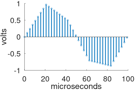
The new sequence then passes through a low-pass digital filter to create a sequence of samples with a foldover frequency that is 8-times higher.
The filter, called an interpolation filter, can be implemented very efficiently - the samples known to be equal to zero do not need to be included in the filter's calculations.
|
Guitar Amplifier Electronics: Circuit Simulation - know your design works by measuring performance at every point in the amplifier. |
Once the sample sequence has been upsampled, it can be processed by nonlinear elements of a guitar amp model. Let's suppose that this creates a harmonic of 38kHz, far above our original 24kHz foldover frequency but well below the upsampled 192kHz foldover frequency.
If a vintage vacuum tube guitar amp creates a 38kHz harmonic, there are no repercussions - the concept of "foldover noise" does not exist. Even if the amp could reproduce 38kHz, the human ear cannot hear it - any harmonic content beyond the limits of hearing is irrelevant. For digital modeling, on the other hand, the situation is quite different.
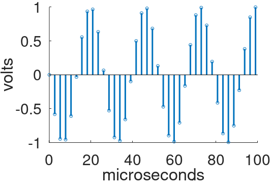
To convert the upsampled output of the guitar amp digital model back to the original 48kHz sample rate, we use a process called decimation, which is problematic for high-frequency harmonics created by distortion. Consider the 38kHz harmonic, as represented by the samples above. For every 8 samples we select the first and throw away the next 7, which represents decimation by a factor of 8. This produces a sequence of samples at the original 48kHz sample rate.
Gee, this looks familiar! Unfortunately, as we saw earlier, if the decimated signal represents a 38kHz signal like this
the DAC will instead create 10kHz foldover noise like this.
The solution is to apply a low-pass, anti-aliasing filter to the sample sequence prior to decimation. The filter removes all frequencies above the new, post-decimation foldover frequency.
Reference
1U.S. Patent 5,789,689.