Digital Modeling of a Guitar Amplifier Power Supply
"The 'feel' of an amplifier is mainly attributed to its dynamic response. Tube amplifiers compress when overdriven due to sagging of the power supply. The amount of sag depends on a variety of factors including the power transformer, type of rectifier used, etc. Deviations in dynamic response can make an amplifier simulation feel too stiff or too spongy in comparison to the real amp." 1 -Fractal Audio Systems
Here we describe a procedure that can be used to create a digital model of a guitar amplifier power supply. As an example, let's use the venerable Fender Deluxe 5E3.
The Deluxe has a pair of 12AY7 triodes in the first stage that draw a total of 2.4mA DC plate current. The second stage 12AX7 triode draws 0.8mA. The phase inverter also draws 0.8mA. The total current load for the preamp and phase inverter is therefore 4mA. The 6V6 screens draw a total of 6mA. The plates idle at 74mA total for both tubes. The total current load on the power transformer at idle (no signal) is thus 4mA + 6mA + 74mA = 84mA.

|
Guitar Amplifier Electronics: Fender Deluxe - from TV front to narrow panel to brownface to blackface Reverb |
Computing the Power Supply DC Output Voltage
Let's use a Hammond 290BX replacement transformer for our model.
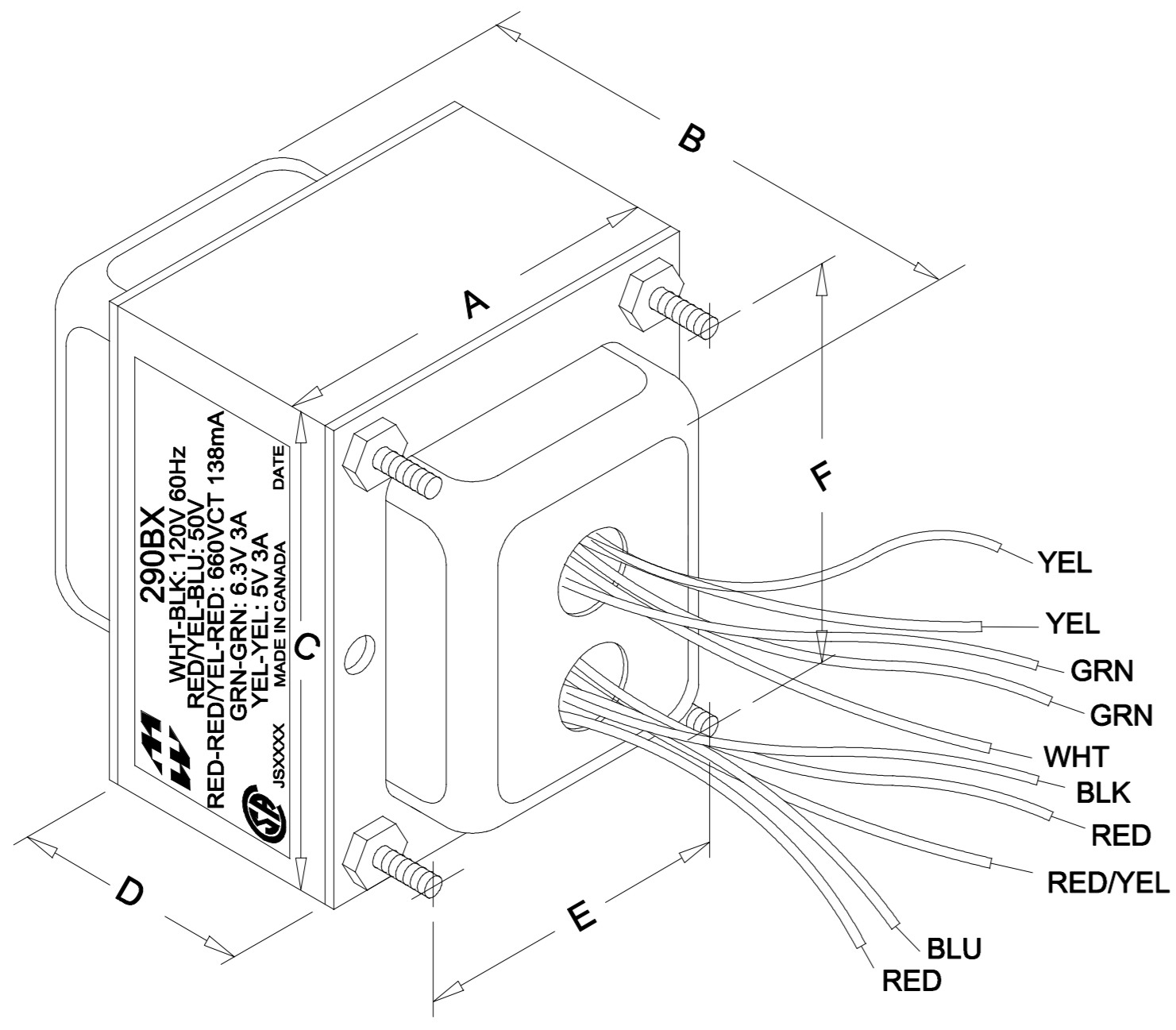
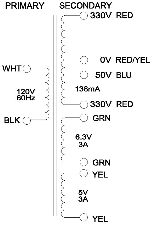
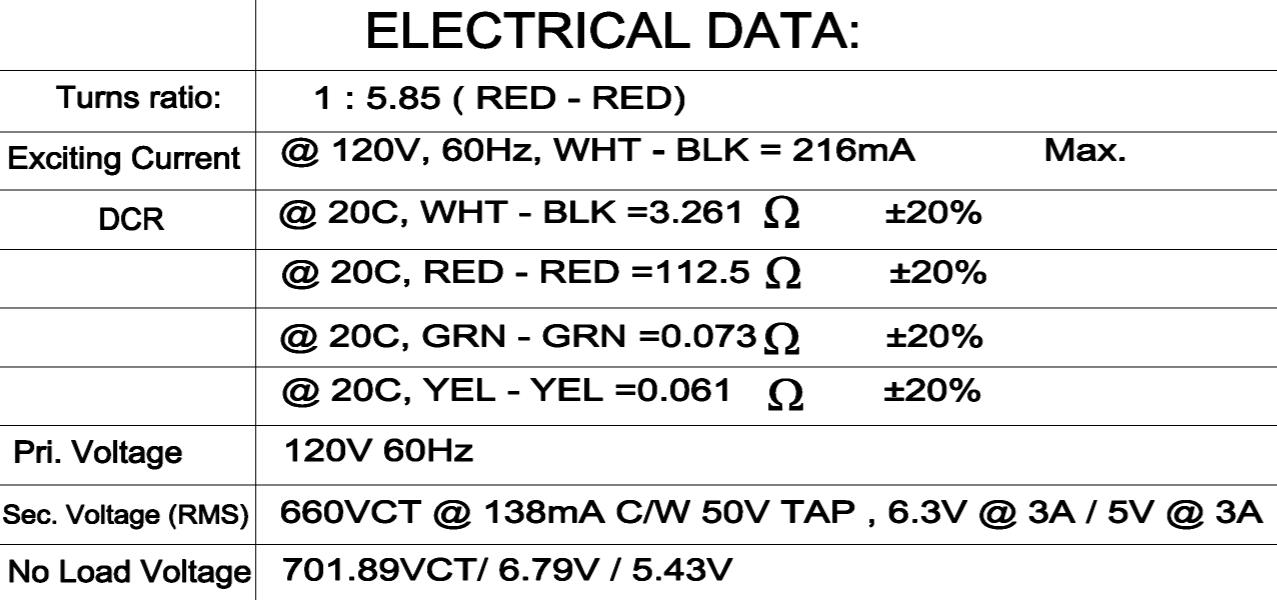
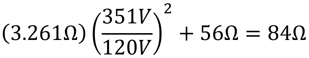
According to Hammond's data sheet, total DC resistance across the secondary (red-to-red) is 112.5Ω, which is 56Ω per phase. The primary winding resistance is 3.261Ω. Without a load, the 120V RMS primary voltage is stepped up to 701.89VCT, i.e. 351V per phase. The total effective resistance per phase in the secondary is therefore2
|
Guitar Amplifier Electronics: Basic Theory - master the basics of preamp, power amp, and power supply design. |
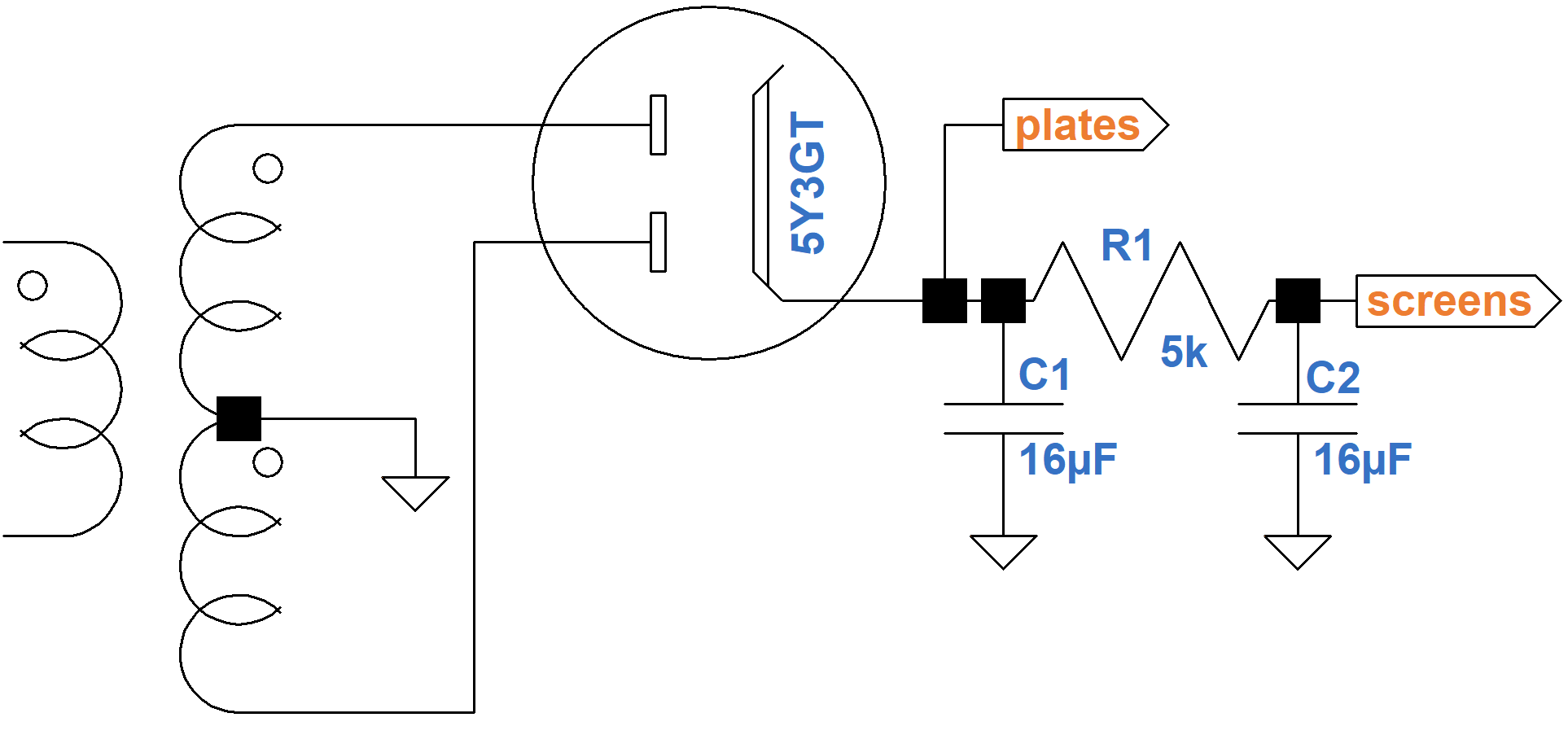
Here are the operation characteristics for the 5Y3GT rectifier tube.
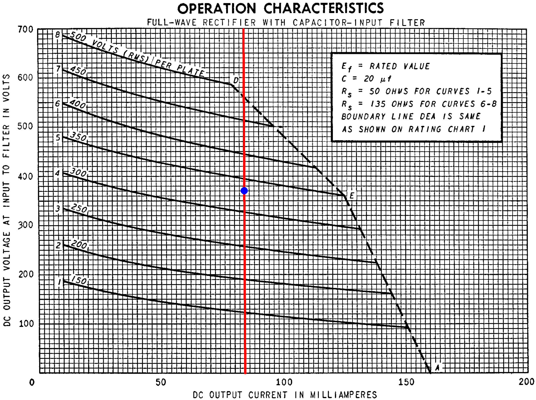
The red line marks the 84mA total DC current. The blue dot marks the point where the line crosses an imaginary 330V RMS curve, which matches the 290BX. The curves assume the DC winding resistance is 50Ω per phase, which is less than the 84Ω we calculated. Moreover, the curves assume a 20μF input capacitor, compared to 16μF for the Deluxe. The DC output voltage is therefore a bit less than the 370V shown on the Y axis for the blue dot. Let's estimate 360VDC for the plate supply under idle conditions.
There is a 4mA + 6mA = 10mA load downstream of the 5kΩ RC filter resistor. According to Ohm's Law, this creates a voltage drop of (10mA)(5kΩ) = 50V. The screen supply voltage is therefore about 310V.
|
Fundamentals of Guitar Amplifier System Design - design your amp using a structured, professional methodology. |
An Analog Model
As the amp's output power level increases, creating more demand for current, the DC power supply voltage sags. The effect is not linear, but according to the 5Y3GT operation characteristics it is close enough to linear for the purposes of developing an analog model. Here the red dot depicts idle conditions. The red line is a linear estimate of DC output voltage versus DC current load.
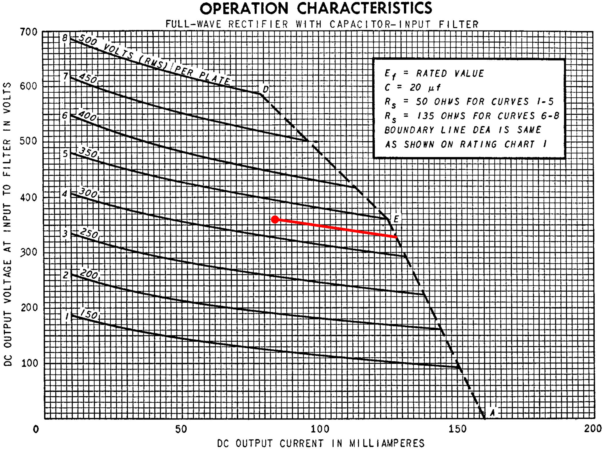
When the current load increases from 84mA to 138mA, the output voltage sags from 360V to 328V. The effective source resistance is therefore
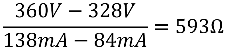
The idle plate supply voltage is 360V for an idle current load of 84mA, so a Thevenin equivalent circuit3 for the power supply has an output impedance of 593Ω and an ideal voltage source of
360V + (84mA)(593Ω) = 410V.
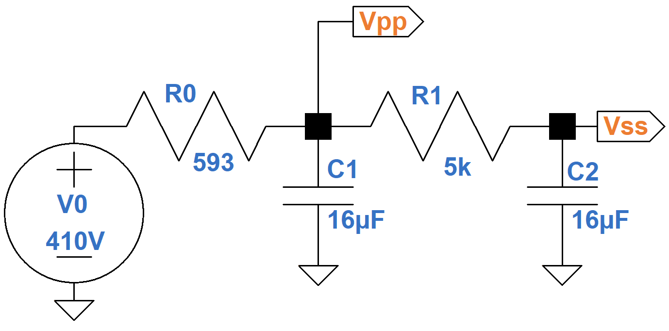
The resulting analog model therefore includes an ideal 410V voltage source and a 593Ω output impedance as shown here.
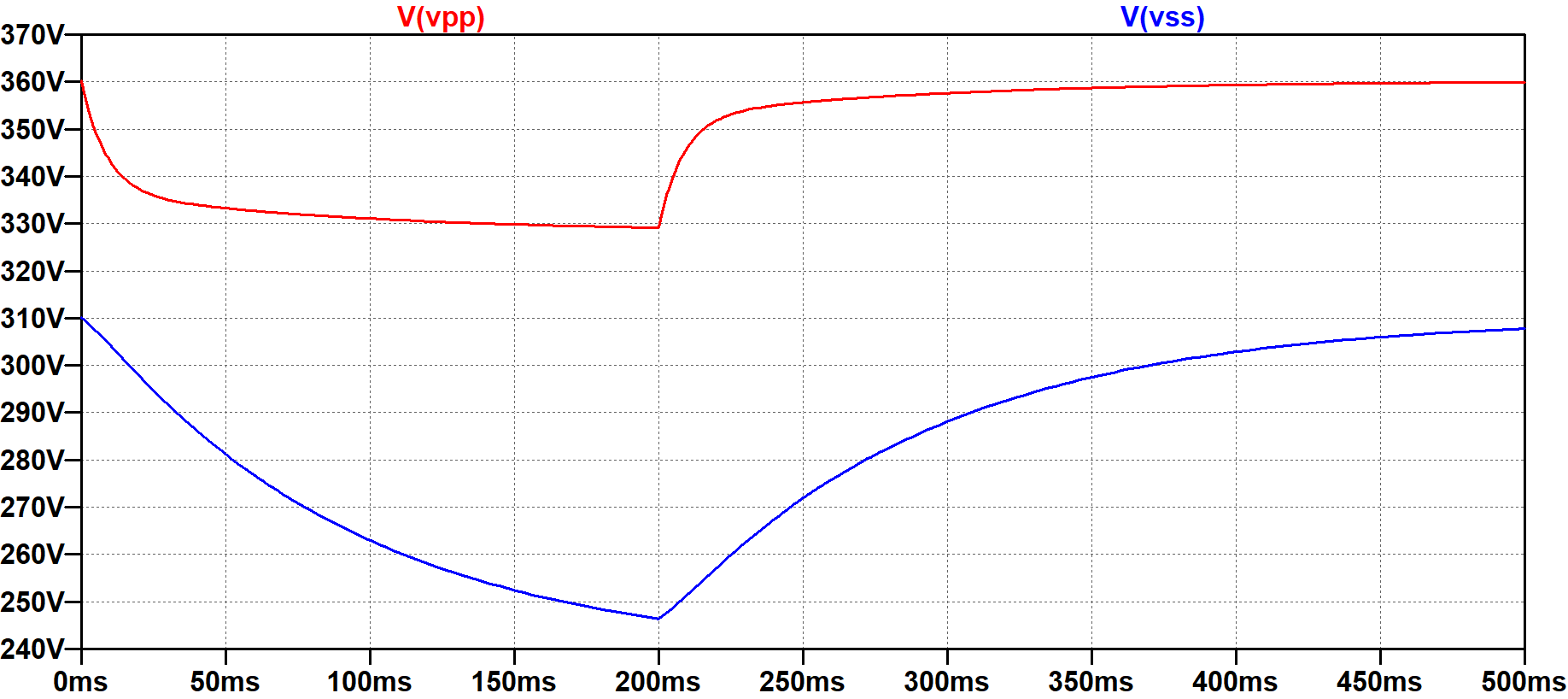
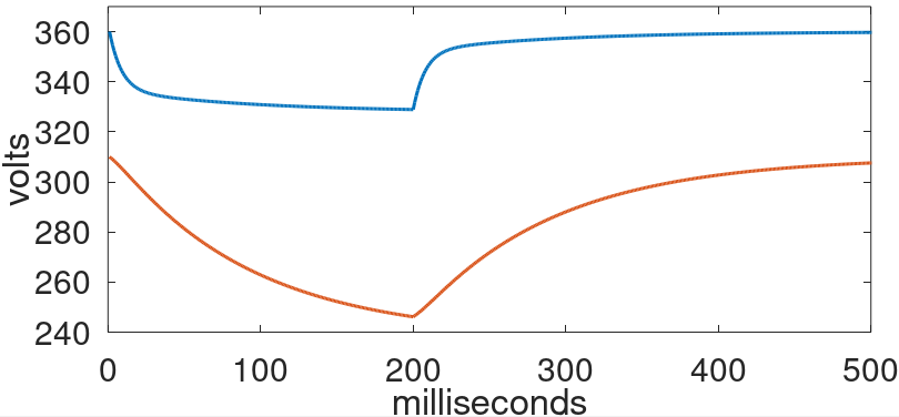
Here is an LTspice simulation4 of a suddenly applied 200-millisecond guitar strum characterized by a plate current increase of 46mA and a screen current increase of 8mA.
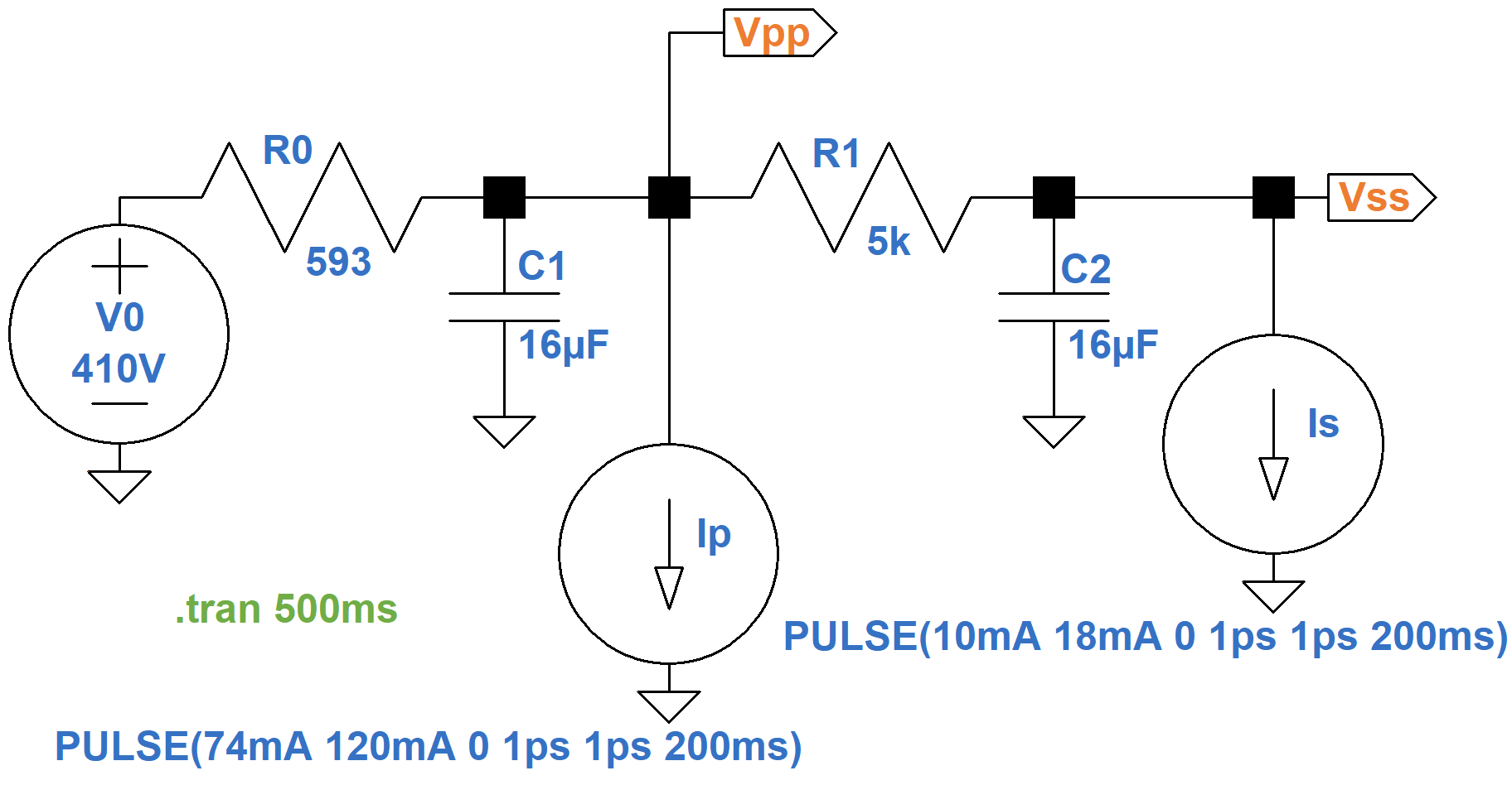
At 200 milliseconds, the signal is removed and the power supply recovers.
The screen supply is effectively downstream of two RC filters: capacitor C1 combined with the power supply output impedance and capacitor C2 combined with R1. It is therefore more susceptible to an increased current load and responds less swiftly.
|
Guitar Amplifier Electronics: Circuit Simulation - know your design works by measuring performance at every point in the amplifier. |
A Digital Model
As a first step toward converting the analog model into a digital model, let's transform the Thevenin equivalent circuit into a Norton equivalent circuit, which uses an ideal current source instead of an ideal voltage source. According to Ohm's Law, the ideal current source is 410V / 593Ω = 691mA.
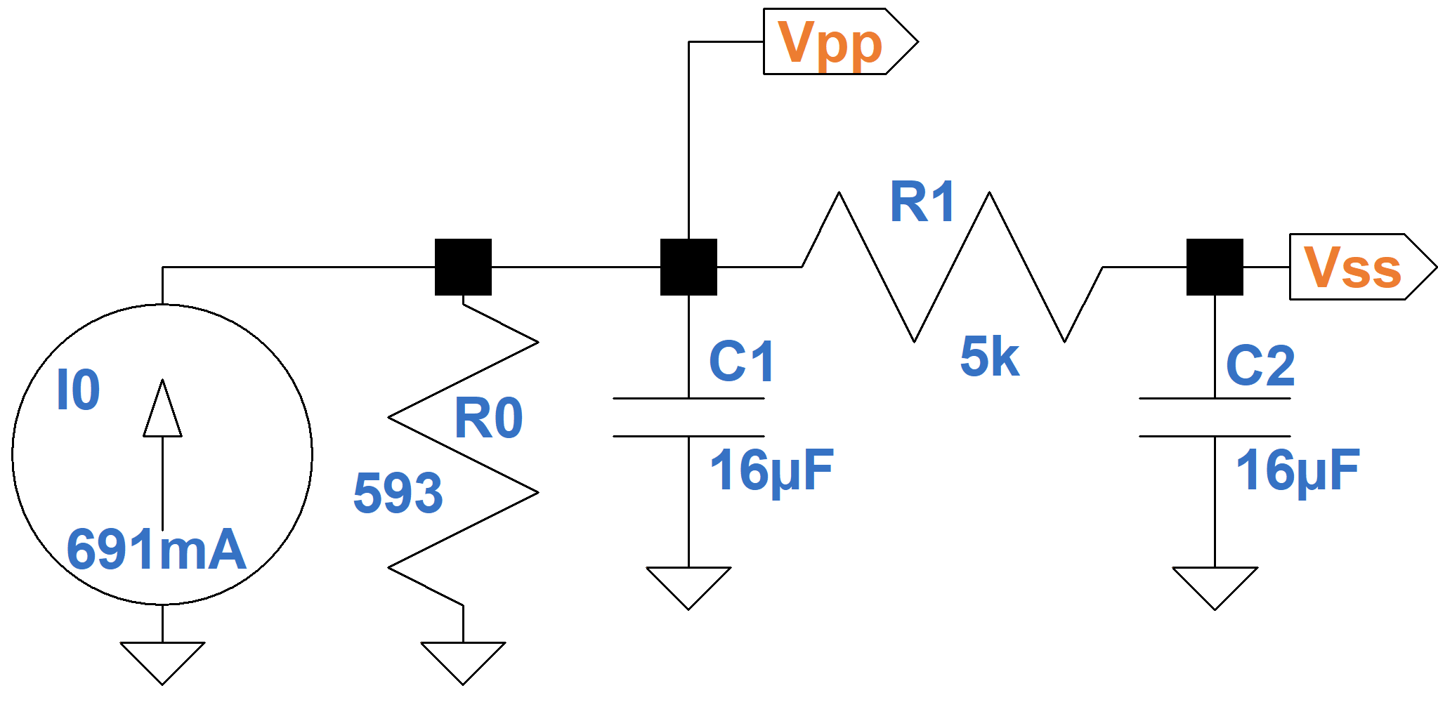
There are two nodes, VPP and VSS. The former supplies plate current IP. The latter has a current load IS, which represents screen current and upstream triode plate current. These current loads are shown in the equivalent circuit below, which is rearranged to focus on the capacitors C1 and C2.
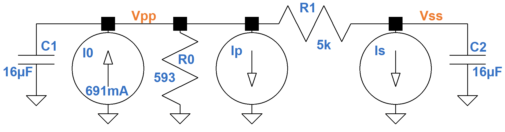
According to Kirchhoff's Current Law, the sum of the currents entering a node equals the sum of the currents leaving a node. The current entering the top of each capacitor is therefore
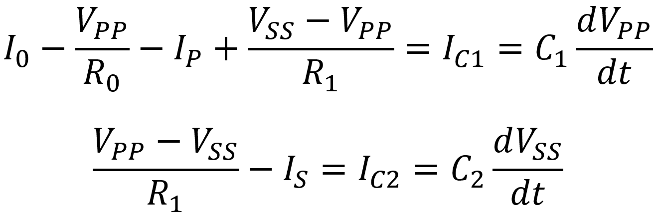
This means that the rate of change in node voltages can be expressed as
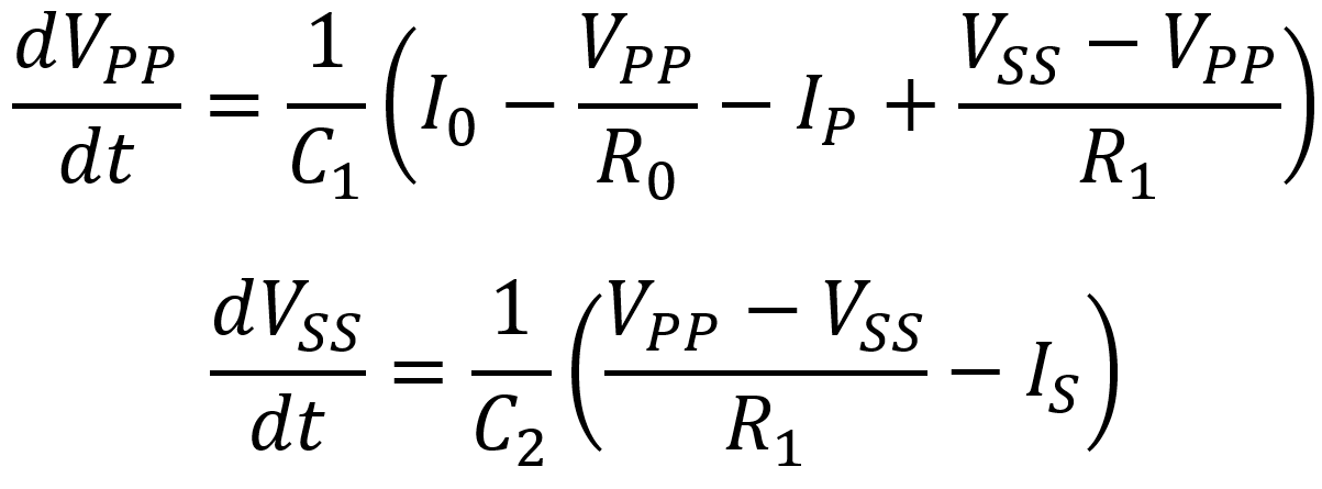
To check these results, let's look at the rate of node voltage change under idle conditions:
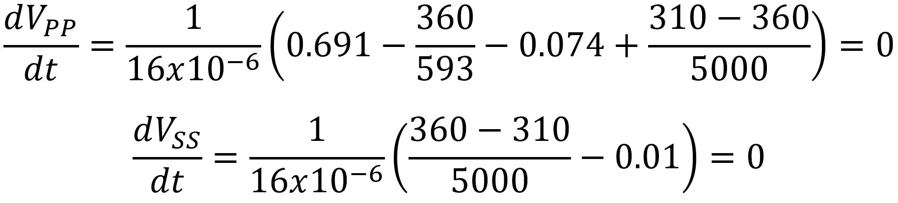
The rates of change for both node voltages are equal to zero. Therefore, as long as the plates draw 74mA and the screens, phase inverter, and preamp continue to draw 10mA, the plate and screen supplies hold steady at 360V and 310V, respectively.
Let's increase the plate and screen loads to 120mA and 18mA, as we did with our SPICE simulation.
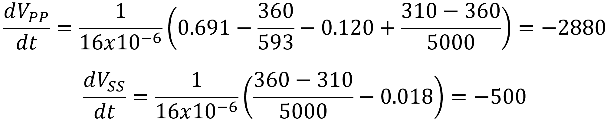
The plate supply sags at an initial rate of 2.88 kilovolts per second (2.88 volts per millisecond). For the screen supply it is a more modest 500 volts per second (0.5 volts per millisecond). If we rerun the SPICE simulation for only the first millisecond or fraction of a millisecond, we see that the supply voltages decrease at initial rates close to these values.
To convert the continuous-time model to discrete time, let's assume a sample rate of 48kHz. This means the sample period is 1/48kHz = 20.83 microseconds. To match our SPICE simulation, if the first sample for the plate supply is 360V, then the second sample is
360V - (2.88kV/s)(20.83μs) = 359.9V
For the screen supply it is
310V - (500V/s)(20.83μs)
which is a tiny fraction lower than 310V. When we plunk the new, slightly lower supply voltages into the two rate formulas, the sag between the second and third samples is slightly less than between the first two samples.
To formalize the concept, here is the discrete-time model based on the sample period Ts.
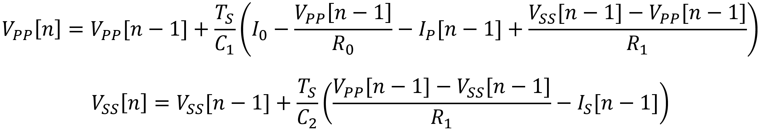
Here we use GNU Octave to repeat the SPICE simulation using discrete samples and the digital model. For direct comparison, the SPICE results are also shown.
References
1Fractal Audio Systems, Multipoint Iterative Matching and Impedance Correction Technology (MIMICTM), April 2013, p. 10.
2Richard Kuehnel, Guitar Amplifier Electronics: Basic Theory, (Seattle: Amp Books, 2018), p. 155.
3Richard Kuehnel, Guitar Amplifier Electronics: Basic Theory, (Seattle: Amp Books, 2018), p. 68.
4Richard Kuehnel, Guitar Amplifier Electronics: Circuit Simulation, (Seattle: Amp Books, 2019).