Digital Modeling of a Guitar Amplifier Tone Stack
"We exhaustively worked out the equations for all the tone stacks by evaluating the mesh and node equations. Fortunately we have computers that handled the polynomial reduction but it was still a Herculean effort." 1 -Fractal Audio Systems
Here we describe the procedure most commonly used to create a digital model of a guitar amplifier tone stack. The formulas are quite lengthy - if you are reading this page with a smartphone, please rotate your display for landscape (horizontal) mode so that they fit on the screen.
David Yeh and Julius Smith have already published a DSP model of a classic Fender Bassman stack.2 Rather than embellish upon their work here, let's model another popular circuit, the James tone stack as found in the Orange Graphic Mk II (1972 version), where it is sandwiched between the first preamp stage and a gain control.
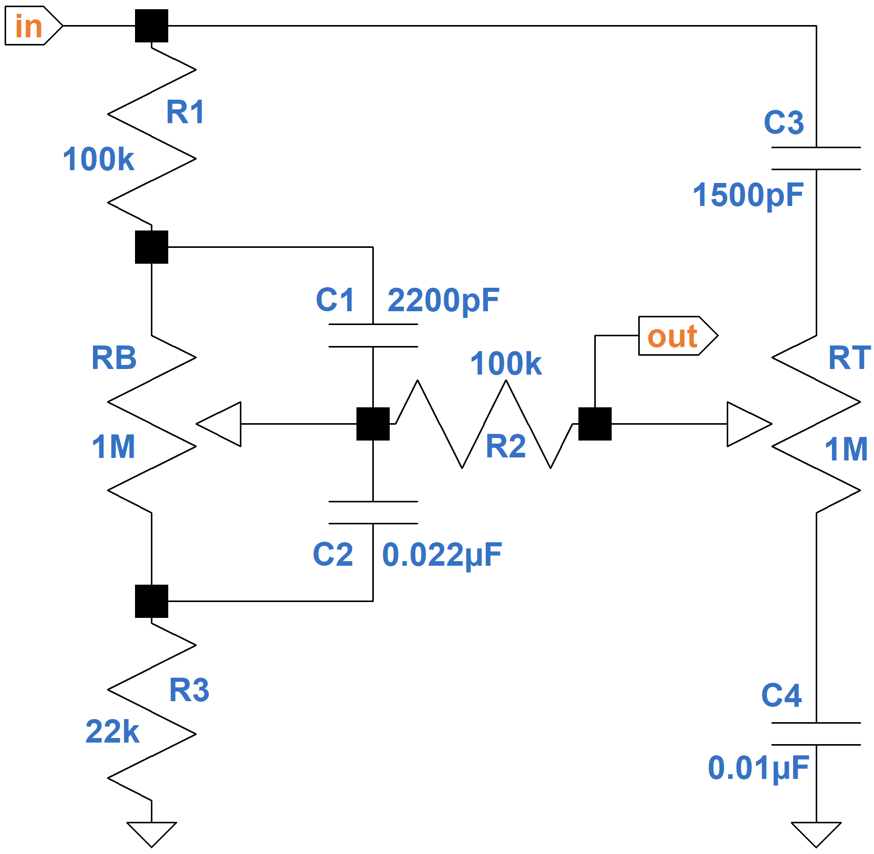
The bass control is on the left. Treble is on the right. The Mk II driving circuit has an output impedance of 50kΩ and the driven circuit has a 1MΩ input impedance, which have a slight impact on performance. We will ignore these details to shorten the equations, which for tone stacks are very large.
Here are the results of a SPICE simulation3 of the analog circuit.
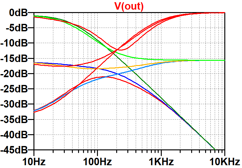
The controls are set to minimum, 15-percent resistance, and maximum. This plot represents a benchmark - the digital model should match these results.
|
Guitar Amplifier Electronics: Fender Deluxe - from TV front to narrow panel to brownface to blackface Reverb |
The Analog Model
Let Z1 represent the impedance formed by the resistance of the bass potentiometer RB above the wiper in parallel with the reactance XC1 of the capacitor C1. Similarly, let Z2 be the resistance below the wiper in parallel with the reactance of C2. We will denote the reactances of C3 and C4 as XC3 and XC4, respectively.
Let's use Kirchhoff's Voltage Law around three loops.
- from ground, through the guitar signal voltage source driving the input, through C3, then the treble control RT, through C4, and back to ground,
- R1, C3, (1-PT )RT, R2, Z1, where PT, which ranges from 0.0 to 1.0, is the position of the treble control and (1-PT)RT is the resistance above the wiper, and
- R3, Z2, R2, PTRT, and C4, where PTRT is the resistance below the treble control wiper.
According to Kirchhoff, here are the three loop equations:
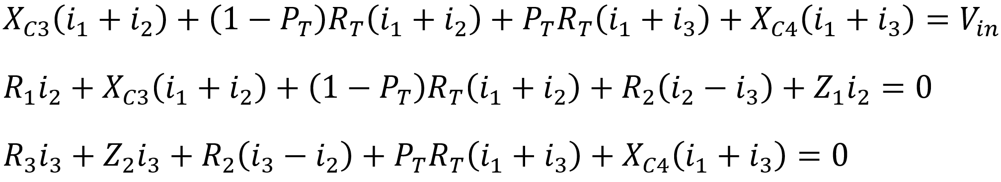
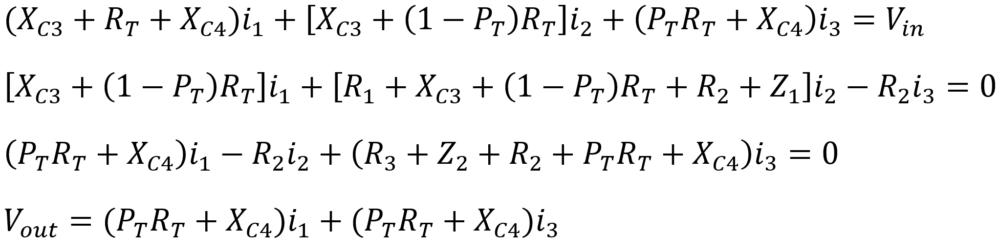
According to Ohm's Law, the output voltage is Vout = (PTRT+XC4)(i1+i3).
Gathering the currents, the four equations become

|
Guitar Amplifier Electronics: Basic Theory - master the basics of preamp, power amp, and power supply design. |
If we use matrices and vectors, these separate equations can be combined into a single formula that can be solved using software, which because of the complexity of the process is the only practical approach. Here is a matrix of impedances, a vector of currents, and a vector of voltages, i.e. Ohm's Law in matrix form:
ZI = V
where Z =
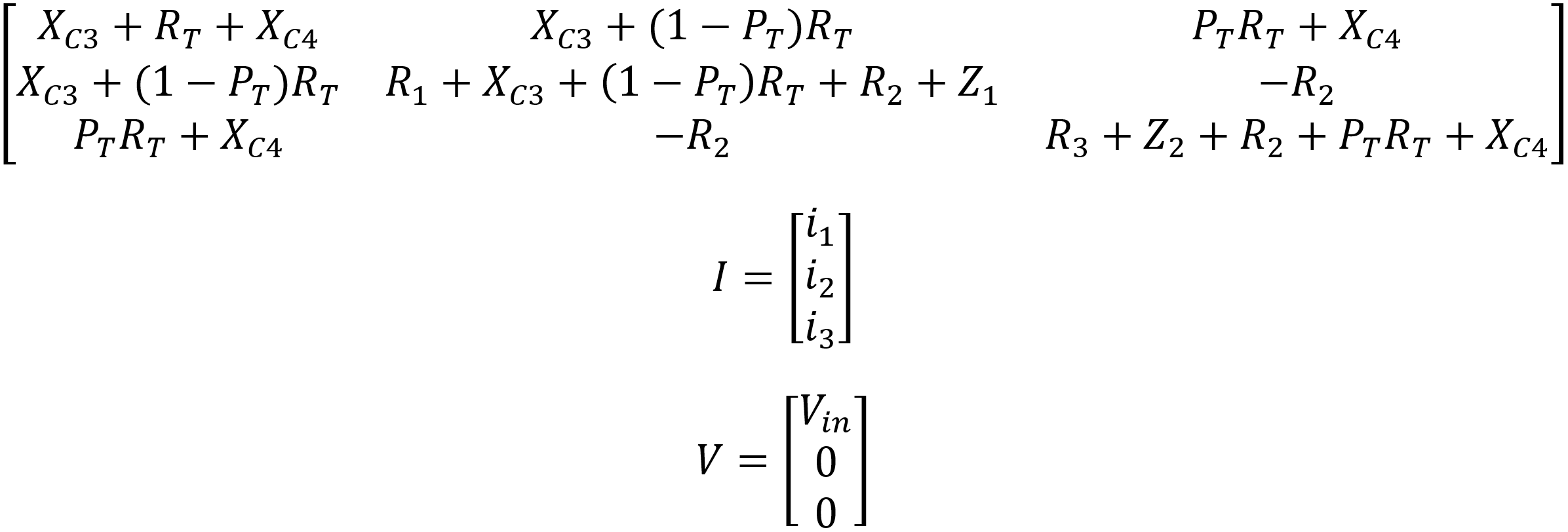
If we invert the 3 by 3 matrix, which is easily performed in software, then I = Z-1V. The output voltage is
Finally, the voltage gain is the output voltage divided by the input voltage:
The actual formula for the inverted matrix Z-1 is enormous, particularly when these substitutions are made:
The formula for H(s) can be entered into software that can manipulate the vectors and invert the matrix symbolically to solve for the gain. Maple, Mathematica, MathCad and some open source packages easily perform this feat. Here we use MathCad. David Yeh and Julius Smith use Mathematica for the Bassman stack.
|
Fundamentals of Guitar Amplifier System Design - design your amp using a structured, professional methodology. |
There are two ways to solve for the gain symbolically. One is to retain the variable names. If the results include the product of, say, R1 and R2, then the final formula for gain contains, literally, "R1R2". This is the approach used by Yeh and Smith, which is handy if part values are subject to change. The other approach, which will be used here, is to substitute the actual part values. In this case the product of the two 100kΩ resistances is a single number: 1010. This approach is usually less verbose and is handy for modeling a specific tone stack in which only the control positions are subject to change.
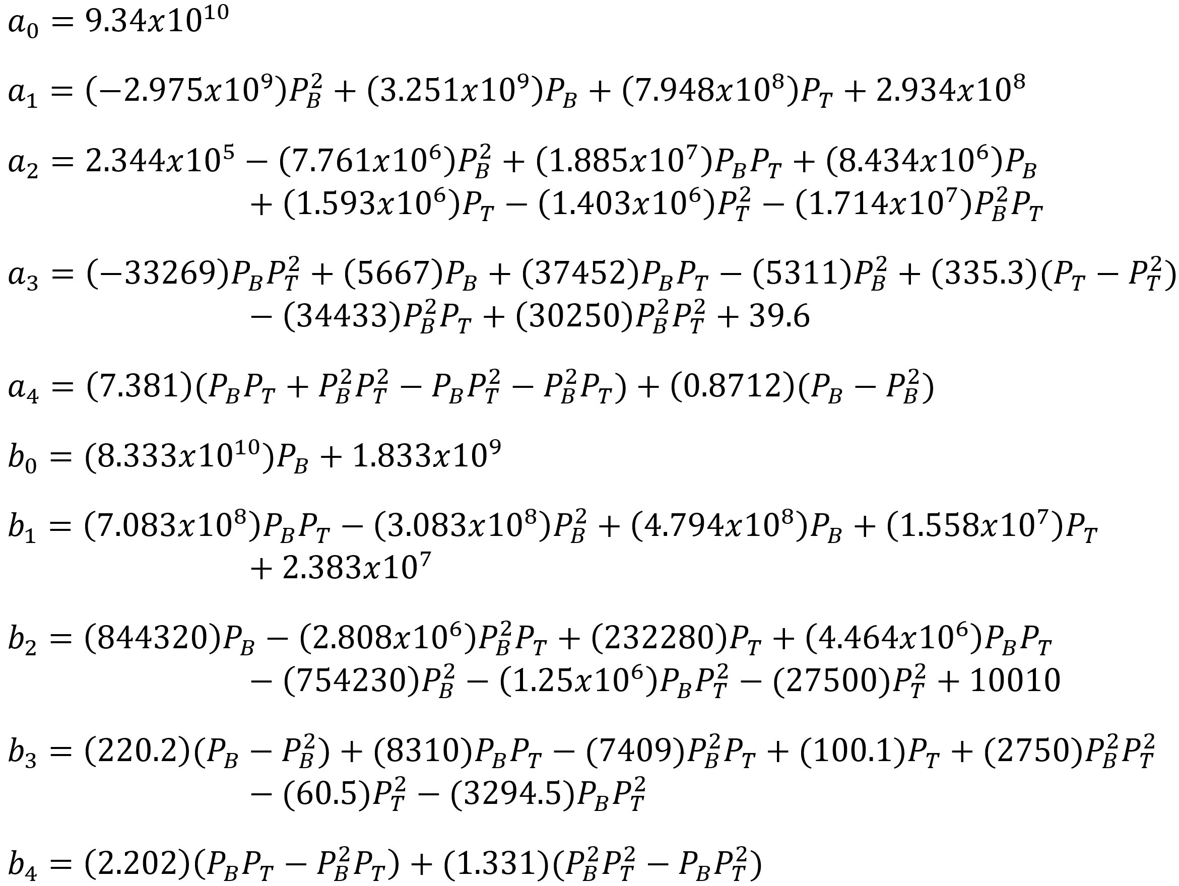
Here is the resulting analog model of the James stack using parts values from the Orange Graphic Mk II (1972 version).
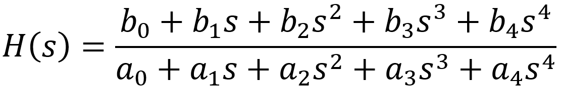
where the coefficients depend only on knob positions:
|
Guitar Amplifier Electronics: Circuit Simulation - know your design works by measuring performance at every point in the amplifier. |
Transforming the Analog Model into a Digital Model
"Simulating drive and tone controls is very difficult and laborious. The equations are onerous and complicated, especially for tone stacks." 4 - Fractal Audio Systems
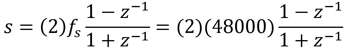
The relationship between the coefficients of the digital filter and the coefficients for the analog filter depends on the sample rate fs. Let's assume a 48kHz sample rate. Using a bilinear transform we substitute this expression for the analog variable s:
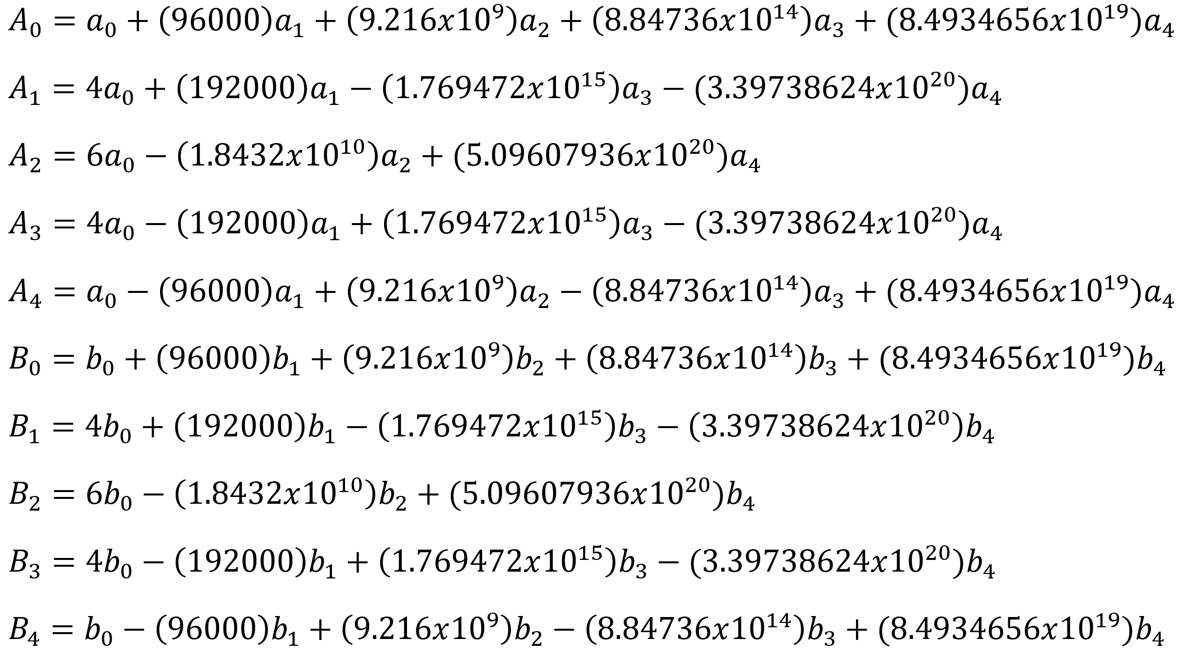
Using math software again to simplify the results, the continuous-time system representation is transformed to a discrete-time representation:
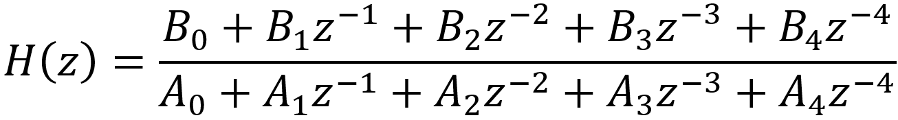
where
The frequency response for the digital filter, as a function of z, is the output divided by the input:
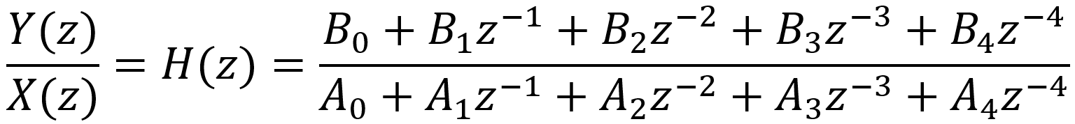
The relationship between the input and output is therefore

Since each z-1 represents a delay of 1 sample (z-2 is a delay of 2 samples, z-3 is a delay of 3 samples, ...), in the time domain we get

This is the formula we use to actually code the digital filter in C++ or the Rust programming language. Specifically, the current output sample is
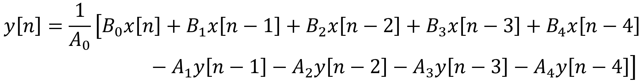
The filter has 8 coefficients that change when the guitar player rotates a knob. When that happens, the analog coefficients a0 ... a4 and b0 ... b4 are recalculated and used to recompute the digital coefficients A0 ... A4 and B0 ... B4. The new digital coefficients are then used to compute the output samples y[n]. In the Line 6 AX2, for example, a microcontroller detects a change in a knob position, computes the updated digital coefficients, and sends them to a digital signal processor that uses them to compute the output samples.5
Here is the frequency response of the digital filter plotted using GNU Octave. To facilitate a direct comparison, the SPICE simulation for the original analog filter is shown in the next plot.
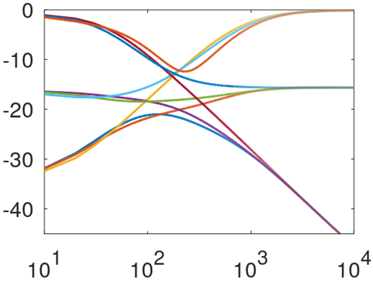
The results are quite accurate for the relatively high 48kHz sample rate. Some deviation at high frequencies can be expected for lower sample rates.
References
1Fractal Audio Systems, Multipoint Iterative Matching and Impedance Correction Technology (MIMICTM), April 2013, p. 7.
2David T. Yeh and Julius O. Smith, "Discretization of the '59 Fender Bassman Tone Stack," International Conference on Digital Audio Effects (DAFx-06), 2006.
3Richard Kuehnel, Guitar Amplifier Electronics: Circuit Simulation, (Seattle: Amp Books, 2019).
4Fractal Audio Systems, Multipoint Iterative Matching and Impedance Correction Technology (MIMICTM), April 2013, p. 7.
5U.S. Patent 5,789,689.