Supro Push-Pull 6973 Power Amp
From the 1940s to the late 1960s, Valco made guitar amps that carried the Supro, National, Harmony, Oahu, Airline, and Gretsch brand names.1 Many were designed around a pair of 6973 beam power tetrodes, including these models:
- the Supro S1624T, S6162, and S6424,
- the Valco 6161, 6400, and 6650TR,
- the Gretsch 6156 Playboy and Model G6162, and
- the Harmony H-430.
Some Supro models are worshiped because of their alleged associations with Jimmy Page and Jimi Hendrix.1 While this is subject to debate, the unique sonic character created by a pair of 6973s is undeniable.
This tube's nine-pin layout and tall, narrow bottle lead plenty of people to assume it "sounds like an EL84," but that's a long way from accurate. Even on paper - physical appearances aside - the 6973 is a very different tube, with maximum plate voltage ratings of around 440 volts DC compared to the EL84's 350 volts, a different pin-out, and different bias requirements. The robustness of this tube implies that you can get a little more juice out of it if you try, and that's certainly the case.2 -Dave Hunter
The Push-Pull Power Amp
Valco 6973 designs generally do not include a screen resistor.
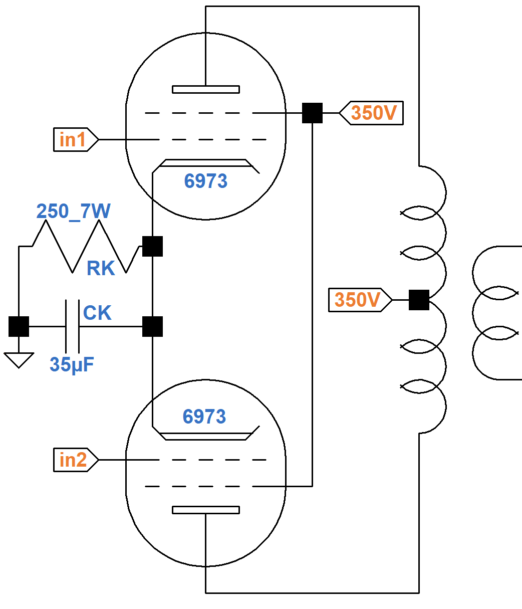
To prevent damage during overdrive, modern designs usually add at least a couple hundred ohms in series with the screens.
|
Guitar Amplifier Electronics: Fender Deluxe - from TV front to narrow panel to brownface to blackface Reverb |
A total of about 92mA (plate current plus screen current for two tubes) passes through the cathode resistor RK to create about 23V at the cathode for a DC grid bias of -23V. The resistor dissipates
(23V)(92mA) = 2.1W
The plate-to-cathode and screen-to-cathode voltages are 327V, which is within the 6973 maximum ratings of 440V and 330V, respectively.
Assuming the tubes operate close to Class B, a 7kΩ plate-to-plate primary can be represented by the blue 1.75kΩ load line shown here, which intercepts an imagined curve for a 327V screen just below the knee.
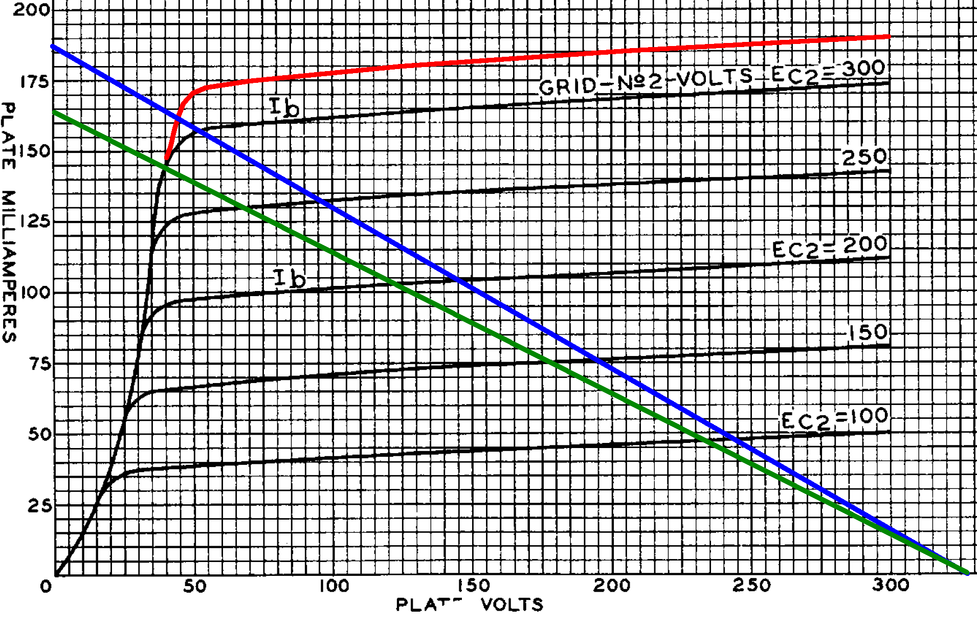
The plate voltage swings positive and negative by
327V - 45V = 282V
Plate current swings by 162mA, for an approximate maximum power level of
(282V)(162mA) / 2 = 23W
The green load line is for 8kΩ plate-to-plate, for which output power is about 21W.
|
Guitar Amplifier Electronics: Basic Theory - master the basics of preamp, power amp, and power supply design. |
The Paraphase Phase Inverter
The Valco design uses a paraphase phase inverter, which consists of two inverting voltage amplification stages separated by an attenuator to compensate for the gain of the second stage.3
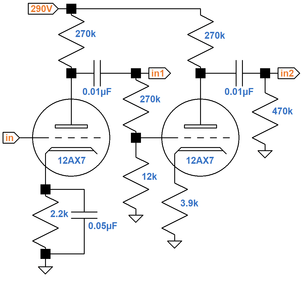
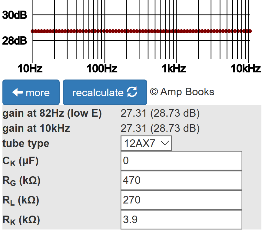
According to the Cathode Bypass Capacitor calculator, the second stage has a voltage gain of 27.3.
The attenuation created by the two resistors at its grid is
12kΩ / (12kΩ + 270kΩ) = 0.426
The voltage gain from in1 to in2 is therefore
(0.426)(27.3) = 1.16
Ideally this should equal 1,
so the power tube at the in2 output is driven slightly more than the
power tube at the in1 output.3
|
Fundamentals of Guitar Amplifier System Design - design your amp using a structured, professional methodology. |
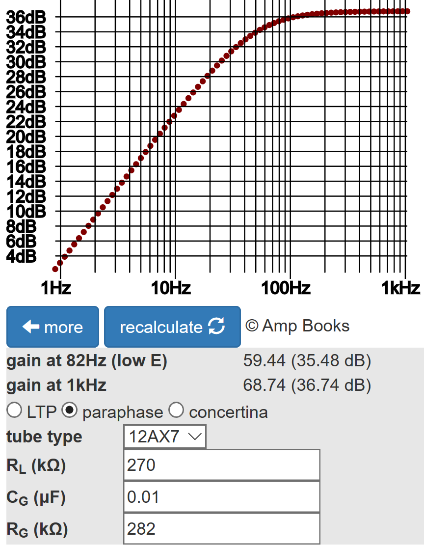
According to the 12AX7 calculator shown below, the plate-to-cathode voltage can swing from its DC value of 167V to its cutoff value of 240V, a difference of
240V - 167V = 73V
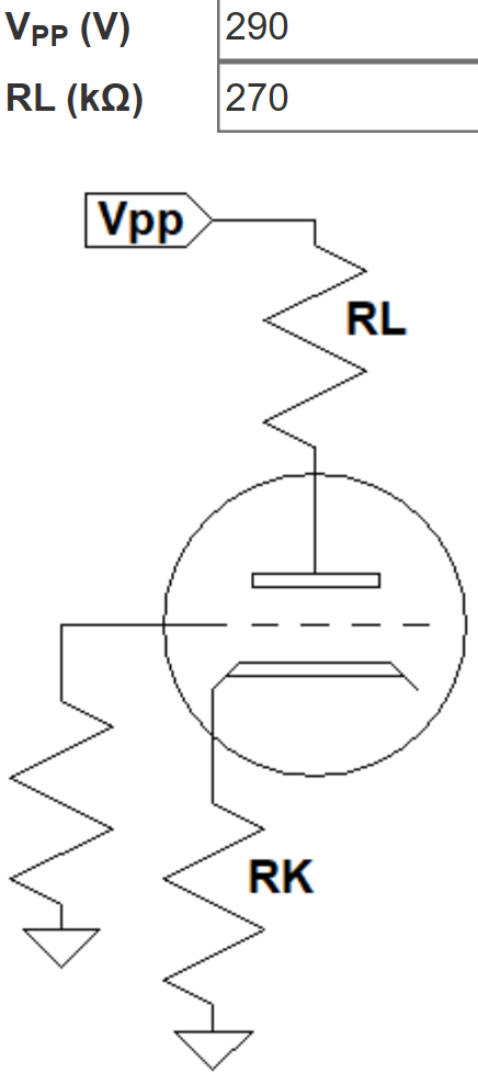
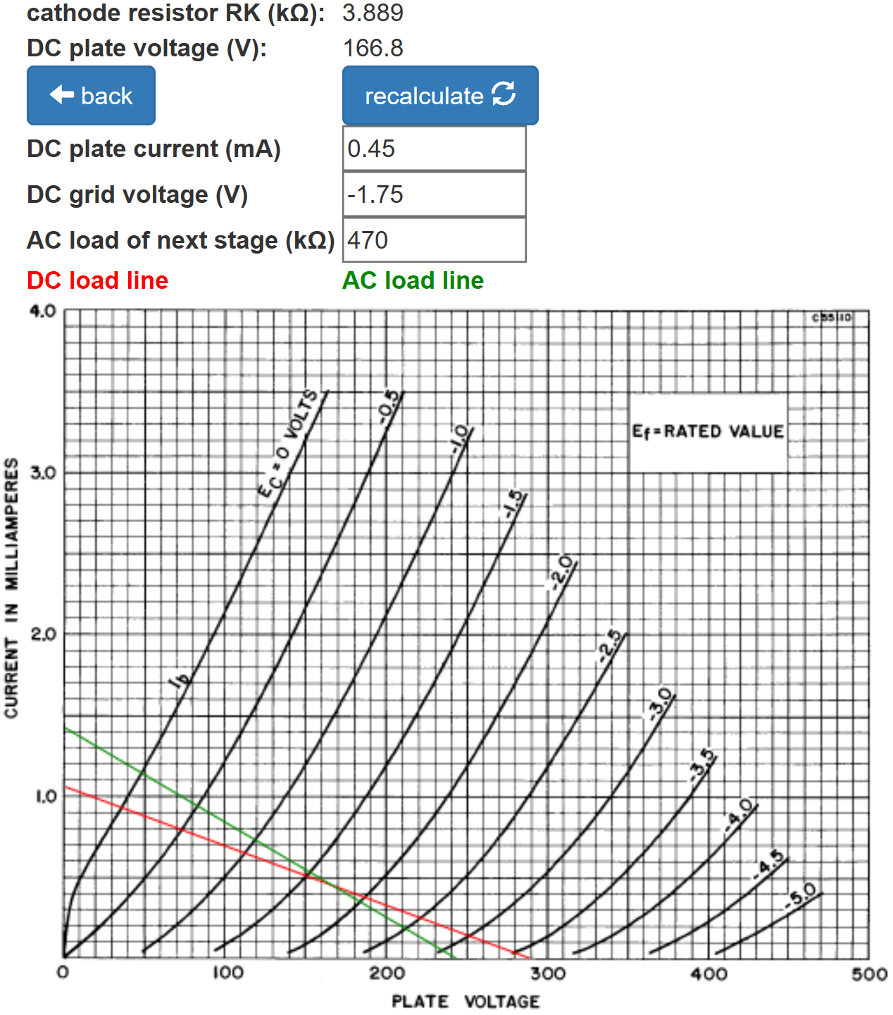
This is much greater than the 23V peak needed to send the power tube to the cusp of overdrive, so the phase inverter has plenty of headroom to drive the power amp to full power.
|
Guitar Amplifier Electronics: Circuit Simulation - know your design works by measuring performance at every point in the amplifier. |
According to the Phase Inverter Bass Response calculator, the 0.01μF coupling capacitor for the second stage creates only 0.6dB attenuation at 82Hz.
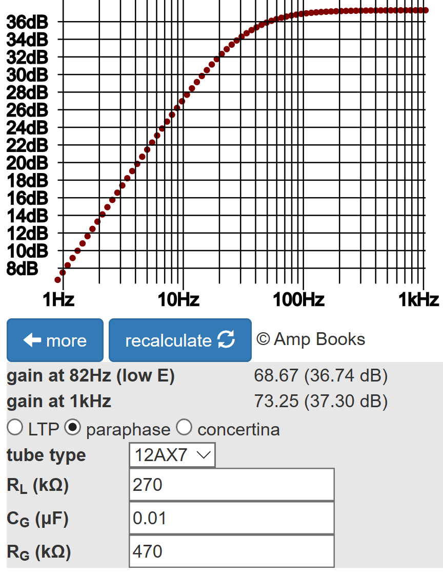
The first stage drives less AC resistance: a total of 282kΩ versus 470kΩ for the second stage. The increased load current creates 1.3dB attenuation at 82Hz.
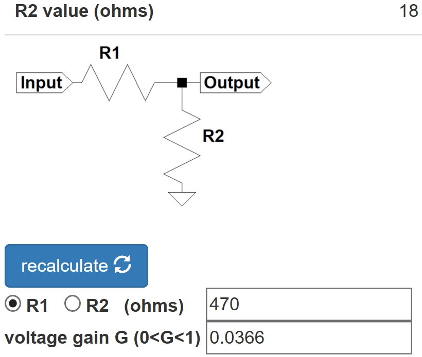
For a more equal bass response, the coupling capacitor value for the first stage can be increased. The more common design choice, on the other hand, is to increase the values of the resistors at the second-stage grid. Ideally, they should attenuate the signal by a factor equal to the reciprocal of second-stage gain:
1 / 27.3 = 0.0366
According to the Voltage Divider calculator, if the series resistor R1 is set to 470kΩ then an 18kΩ value for the shunt resistor R2 does the job.
Making these kinds of changes can turn out to be a mistake, however. Eliminating a slight imbalance in bass response and gain might be well recommended for a HiFi amp, but correcting perceived technical imperfections in a guitar amp can have undesirable sonic consequences. Circuit designer beware!
References
1Dave Hunter, Amped, (Minneapolis: Voyageur Press, 2012), p. 108.
2Dave Hunter, Amped, (Minneapolis: Voyageur Press, 2012), p. 136.
3Richard Kuehnel, Guitar Amplifier Electronics: Basic Theory, (Seattle: Amp Books, 2018), pp. 126-130.